Processing method of upper shaft used for steering apparatus

A processing method and technology for a steering device, which are applied in the steering column, steering control mounted on a vehicle, transportation and packaging, etc., can solve the problems of reduced processing precision and processing speed, complex device structure, and large material consumption. The effect of improving machining precision, saving material and increasing machining speed

Active Publication Date: 2009-08-05
KOWOO
View PDF0 Cites 2 Cited by
  • Summary
  • Abstract
  • Description
  • Claims
  • Application Information

AI Technical Summary

Problems solved by technology

[0005] In such a steering device, usually, the upper end shaft of the automobile is formed hollow by turning or broaching. At this time, the structure of the device is complicated, and the hollow shaft is formed from the real shaft, so the material consumption is large and the processing is precise. Reduced speed and processing speed

Method used


Image

  • Processing method of upper shaft used for steering apparatus
  • Processing method of upper shaft used for steering apparatus
  • Processing method of upper shaft used for steering apparatus

Examples


Embodiment Construction

[0024] The method for machining the upper end shaft of the steering device in the embodiment of the present invention will be described below.

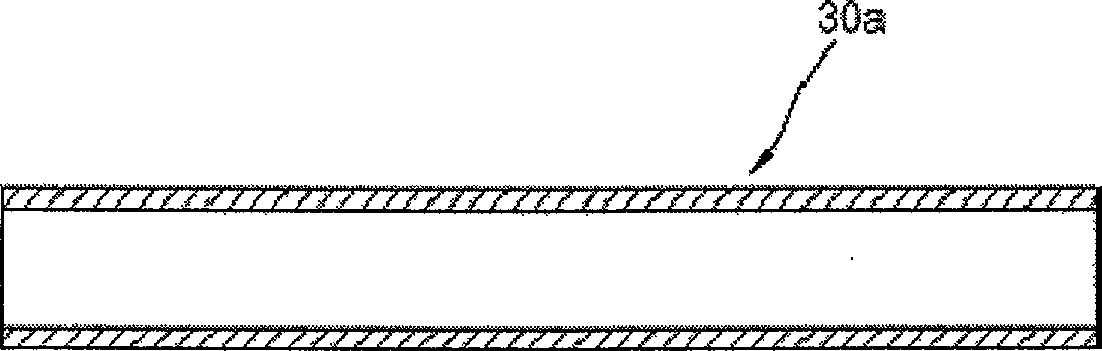
[0025] refer to Figure 4g , the upper end shaft 30 includes: a first joint part 31 combined with a hexagonal cross-sectional shape of the steering wheel; a second joint part 33 formed with an inner diameter keyway (spline) and combined with the lower end shaft; formed on the first and second joint parts 31 , 33 between the tapered portion 32.

[0026] Figure 5 to Figure 7 It is a schematic diagram of a preferred processing device for realizing the processing method in the present invention, Figure 5a to Figure 5f respectively Figure 7 Cross-sectional views of A-A line, B-B line, C-C line, D-D line, E-E line and F-F line.

[0027] The processing method in the embodiment of the present invention is as Figure 7 , the gradually deformed deformation shafts (30b-30f) are sequentially moved and inserted on the fixed block 10 for pr...


PUM


Abstract

The invention relates to a method for processing an upper end shaft of a steering device capable of improving the processing density, saving cost of materials and improving the processing speed. The processing method comprises processing a cylindrical tube (30a) into first to second deformative shafts sequentially to obtain the upper end shaft finally. The method for processing the upper end shaft reduces thickness of a hollow tube and prolongs a length sequentially, and an inner key slot is formed by inserting a spindle having key slot, thereby improving the processing precision, saving materials, and improving the processing speed.

Description

technical field [0001] The invention relates to a processing method for an upper shaft of a steering device, in particular to a processing method for an upper shaft of a steering device that can increase processing density, save material costs, and increase processing speed (upper shaft manufacturing method) for steering apparatus). Background technique [0002] Usually, in order to cope with collisions with other vehicles or other external structures or rear-end collisions while driving, various vehicles have safety devices, for example, the steering system is provided with shocks that absorb or buffer the impact (that is, by deforming the steering column ( column)) to reduce the impact force on the chest due to the movement of the driver during a collision. [0003] refer to figure 1 and figure 2 The impact absorbing structure of the steering system that buffers the impact force through the deformation of the steering column as described above includes: it is accommoda...

Claims


Application Information

Patent Timeline
Patent Type & Authority Applications(China)
IPC IPC(8): B21K1/12B62D1/19
CPCB21D22/16B21D25/00B21D31/00B21D41/04B21D53/88
Inventor 慎泰重
Owner KOWOO
Why Eureka
Try Eureka