Anti-floating construction method for cast-in-place concrete hollow building roof

A hollow floor and construction method technology, applied to the processing of building materials, structural elements, building components, etc., can solve the problems of inability to control more accurately and effectively, troublesome construction, and not easy to find

Inactive Publication Date: 2009-08-05
吴建辉
View PDF0 Cites 11 Cited by
  • Summary
  • Abstract
  • Description
  • Claims
  • Application Information

AI Technical Summary

Problems solved by technology

In the past, it was troublesome to use iron wire to connect the lower part of the formwork, and the thickness of the upper and lower protective layers could not be accurately controlled. In addition, the iron

Method used


Image

  • Anti-floating construction method for cast-in-place concrete hollow building roof
  • Anti-floating construction method for cast-in-place concrete hollow building roof

Examples


Embodiment Construction

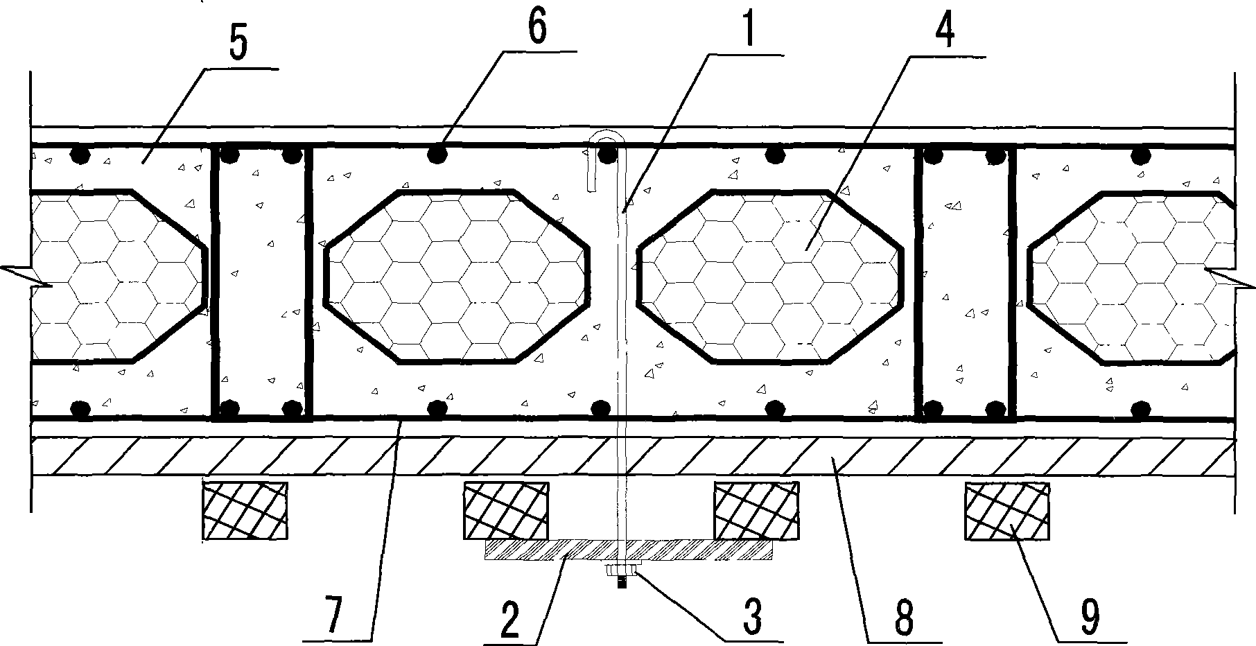
[0011] This construction method is realized in the following manner:

[0012] 1. Make steel tie rods (1) and bearing plates (2); install nuts and gaskets (3) corresponding to the threaded ends of the steel tie rods.

[0013] 2. Bind the lower reinforcing bars (7) of the hollow slab, lay the filling material (4), and bind the upper reinforcing bars (6) of the hollow slab.

[0014] 3. According to the anti-floating point layout requirements in the construction organization, drill holes on the formwork (8) at a certain interval.

[0015] 4. The hooks are hung at the long and short intersections of the upper steel bars (6), and the pressure bearing plate (2) is placed perpendicular to the formwork cross brace purlins (9), and then the upper and lower distances are determined according to the relevant plate thickness, and the pressure bearing plate (2) is tightened The following nut (3) fixes the reinforcing bar tie rod (1) on the cross brace purlin (9).

[0016] 5. Pouring concr...


PUM


Abstract

The invention relates to a floatation resistant construction method of a cast-in-site concrete hollow floor system. The cast-in-site concrete hollow floor system consists of a reinforced steel tie rod of which one end of is hooked on reinforced steel ribs while the other end is fixed on transverse bracing purlines, a load-bearing plate, nuts and gaskets. The invention can accurately control the thicknesses of cast-in-site hollow slabs and has strong floatation resistance; the invention ensures that floatation resistant points are fewer and more accurate compared with the prior floatation resistant technology, has simple construction and can ensure the construction quality. The invention is suitable for the engineering having suspended ceiling requirement and the reinforced steel tie rods can be used as tie rods of suspended ceilings at the late stage as well.

Description

Technical field [0001] The invention relates to an anti-floating construction method of a cast-in-place concrete hollow slab, which belongs to the field of general building structures. Background technique [0002] In the field of construction, with the increasing number of long-span concrete structures, more and more floor slabs use concrete hollow floor technology. Cast-in-situ concrete hollow floors have the problem of anti-floating during construction. In the past, it was troublesome to use iron wires to connect the lower part of the formwork, and the thickness of the upper and lower protective layers could not be accurately controlled. In addition, the iron wires were easy to vibrate and break when pouring concrete (sometimes the iron wires were already broken when they were tightened) and were not easy to find, so they could not be controlled more accurately and effectively. [0003] If a reasonable construction technique can be adopted to reduce the construction time...

Claims


Application Information

Patent Timeline
IPC IPC(8): E04G21/00E04C5/18
Inventor 吴建辉
Owner 吴建辉
Why Eureka
Try Eureka