Electromagnetic valve
A solenoid valve and valve seat technology, applied in the field of solenoid valve, can solve the problems of unreliable action, increase the cost of solenoid valve, increase material cost, etc., and achieve the effect of improving reliability
- Summary
- Abstract
- Description
- Claims
- Application Information
AI Technical Summary
Problems solved by technology
Method used
Image
Examples
Embodiment 1
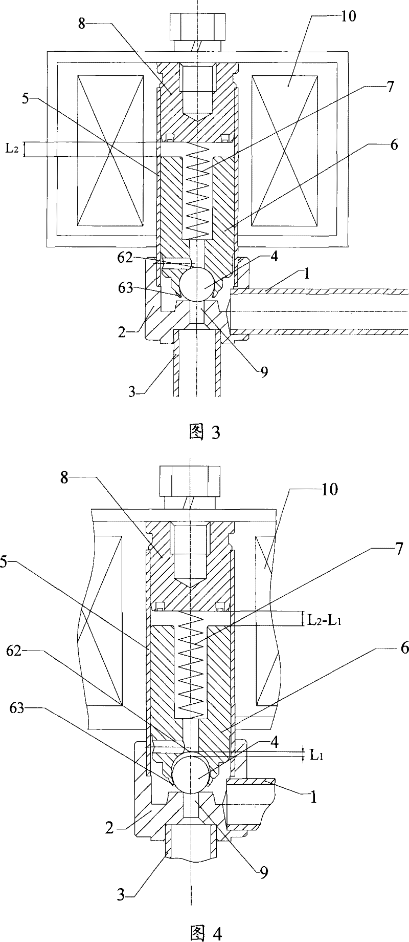
[0041] This embodiment discloses a solenoid valve structure in which the sealing member is a ball type as a preferred specific implementation manner. The following is attached Figure 3 to Figure 5 Be explained.
[0042] image 3 It is a schematic diagram of the structure of the solenoid valve in this embodiment when it is in a closed state, Figure 4 It is a schematic diagram of the local structure of the steel ball leaving the valve port in this embodiment, Figure 5 It is a schematic diagram of the partial structure of the moving iron core and the static iron core in this embodiment.
[0043]like image 3 As shown, the solenoid valve in this embodiment includes: a valve seat 2, a sleeve 5 connected to the valve seat 2 and a coil 10 outside the sleeve 5, the coil 10 is energized or de-energized to control the opening or closing of the solenoid valve, and the valve seat 2 There is a valve port 9 and the medium inlet pipe 1 and outlet pipe 3 are welded and fixed, the inle...
Embodiment 2
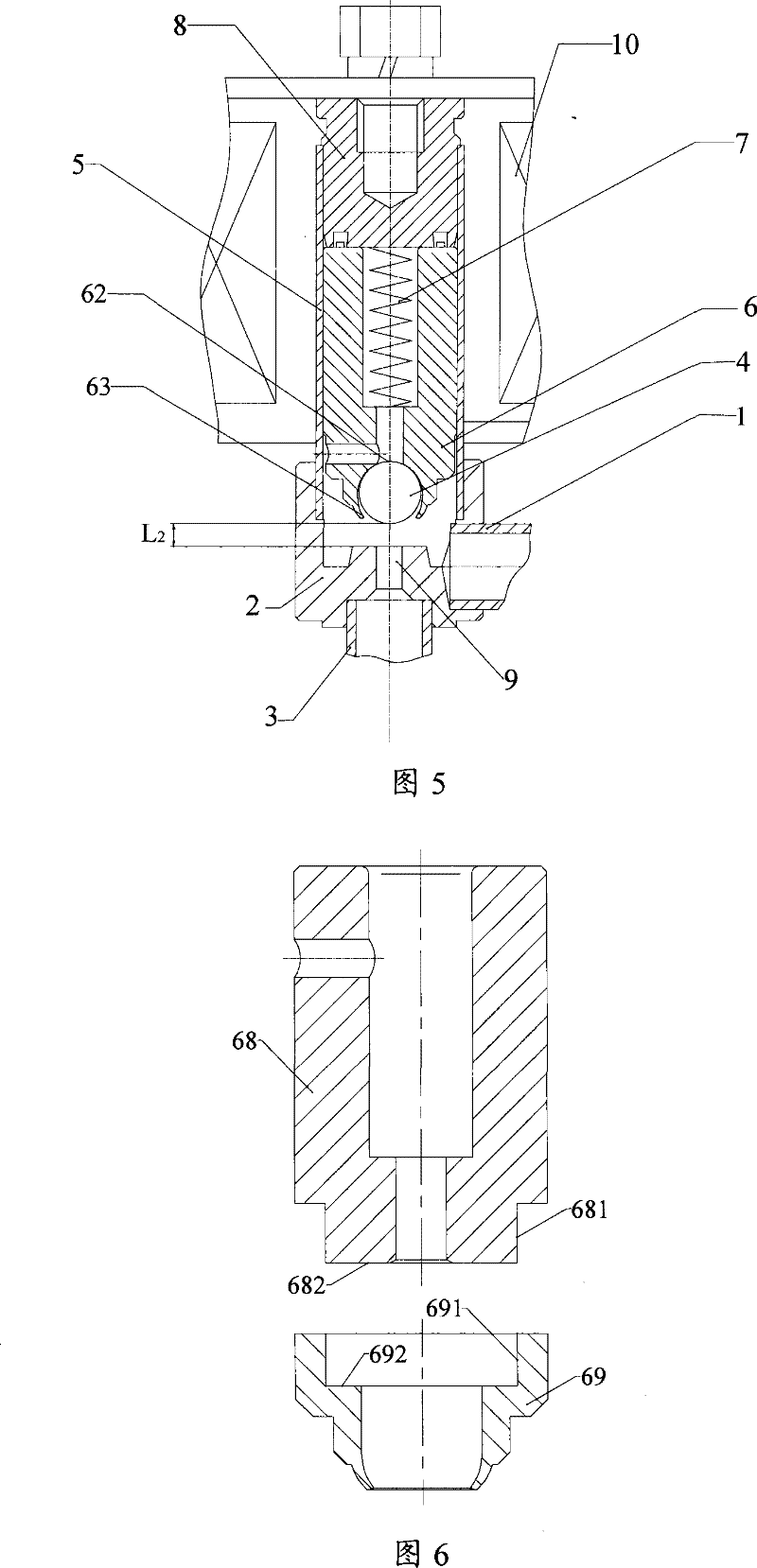
[0051] This embodiment combines Image 6 , Figure 7 , Figure 8 A more preferred embodiment is disclosed, Image 6 It is a schematic diagram of the decomposition structure of the moving iron core in this embodiment, Figure 7 Yes Image 6 The schematic diagram of the overall structure of the moving iron core, Figure 8 It is a structural schematic diagram of the closed state of the solenoid valve in this embodiment.
[0052] The difference from the foregoing embodiments is that the moving iron core 6' includes two parts: a soft magnetic permeable body 68 and a non-magnetic seal fixing part 69, the magnetic permeable body 68 is made of soft magnetic materials, and the seal fixing part 69 is made of Composed of non-magnetic materials.
[0053] like Image 6 and Figure 7 As shown, the magnetic conduction body 68 and the seal fixing part 69 are press-fitted into one body through interference fit. After press-fitting, the end face 682 of the magnetic conduction body 68 an...
Embodiment 3
[0059] Further, in order to more reliably ensure the tight connection between the magnetically permeable body 68 and the seal fixing part 69 in the above-mentioned second embodiment, a groove 683 can be provided on the outer surface of one end of the magnetically permeable body 68, and the seal A protrusion 693 is provided on the inner surface of the fixing portion 69 , so that the groove 683 cooperates with the protrusion 693 to fix. This embodiment combines Figure 9 Disclosed is a matching connection mode between the magnetically permeable body of the moving iron core and the fixing part of the seal.
[0060] Figure 9 It is a structural schematic diagram of the moving iron core described in this embodiment. like Figure 9 As shown, a groove 683 is provided on the outer surface of one end of the magnetic conduction body 68. After the seal fixing part 69 is pressed into the magnetic conduction body 68, the seal fixing part 69 and the magnetic conduction body 68 are presse...
PUM
 Abstract
Description
Claims
Application Information
 - R&D
- Intellectual Property
- Life Sciences
- Materials
- Tech Scout
- Unparalleled Data Quality
- Higher Quality Content
- 60% Fewer Hallucinations
Browse by: Latest US Patents, China's latest patents, Technical Efficacy Thesaurus, Application Domain, Technology Topic, Popular Technical Reports.
© 2025 PatSnap. All rights reserved.Legal|Privacy policy|Modern Slavery Act Transparency Statement|Sitemap|About US| Contact US: help@patsnap.com


