Current mirror circuit with feedback regulation and method thereof

A technology of current mirroring and feedback adjustment, which is applied in the direction of adjusting electrical variables, control/regulation systems, instruments, etc., and can solve problems such as current errors

Inactive Publication Date: 2009-08-05
IPGOAL MICROELECTRONICS (SICHUAN) CO LTD
View PDF0 Cites 18 Cited by
  • Summary
  • Abstract
  • Description
  • Claims
  • Application Information

AI Technical Summary

Problems solved by technology

For example, in a circuit with a reference current of 100uA, it may cause a current error of 0.5u (0.5%)

Method used


Image

  • Current mirror circuit with feedback regulation and method thereof
  • Current mirror circuit with feedback regulation and method thereof
  • Current mirror circuit with feedback regulation and method thereof

Examples


Embodiment Construction

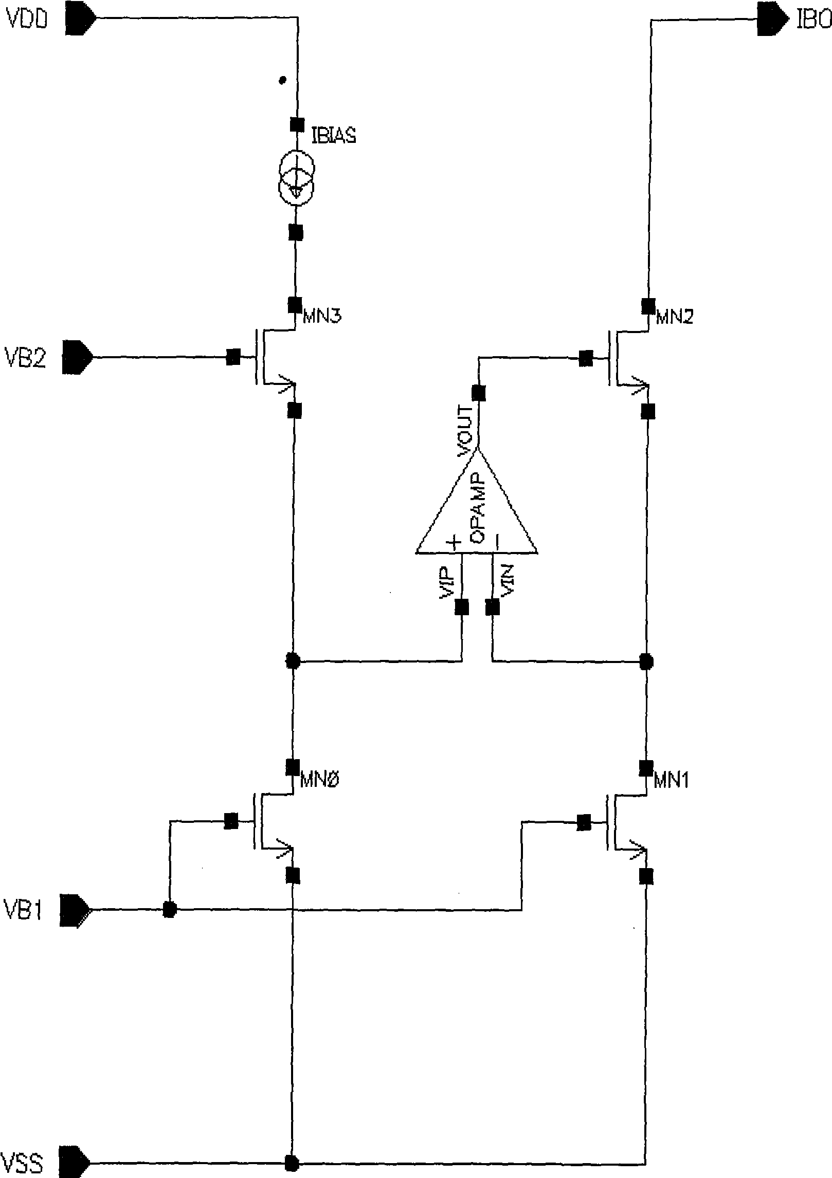
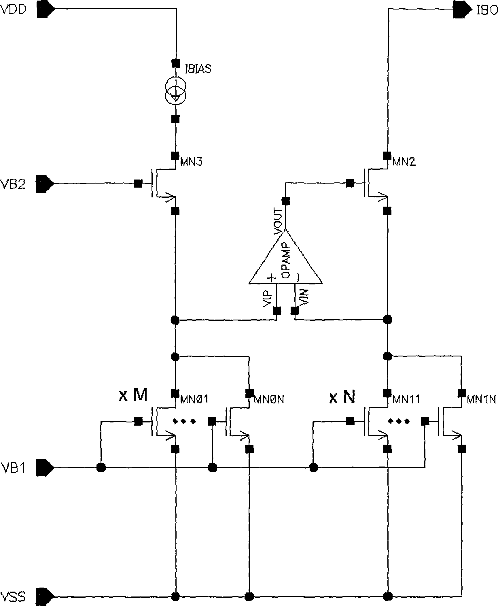
[0025] Such as Figure 2-6 Shown, where OPAMP is an operational amplifier, its positive terminal is P, and its negative terminal is N.

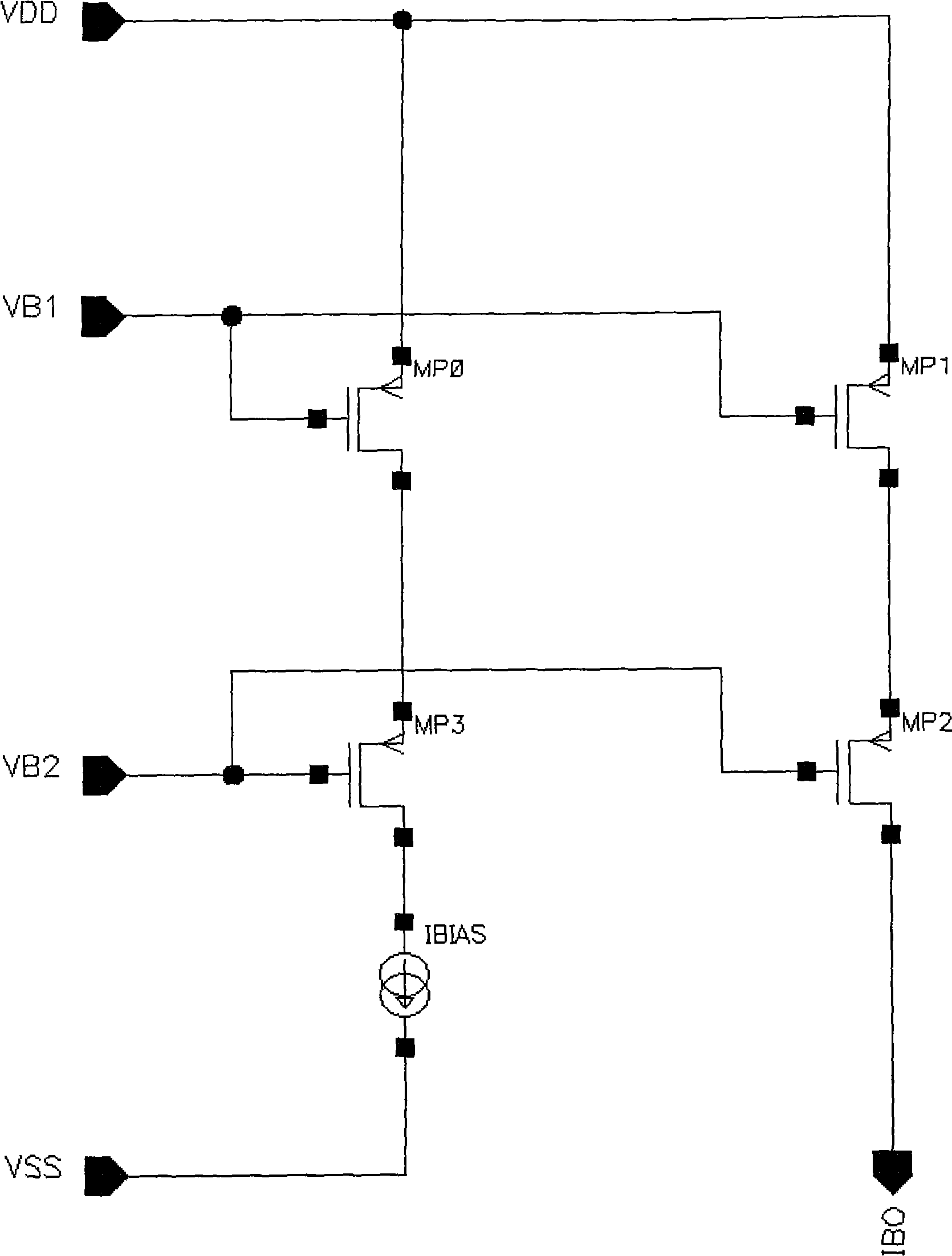
[0026] A current mirror circuit with feedback regulation, including a mirrored MOS transistor and a mirrored MOS transistor, the gate terminals of the mirrored MOS transistor and the mirrored MOS transistor are connected to a fixed bias voltage, the source terminal is connected to a power supply or ground, and the drain terminals are respectively cascaded MOS The drain terminal is connected to the input terminal of the operational amplifier at the same time, and the output terminal of the operational amplifier is connected to the cascaded MOS tube.

[0027] The mirrored MOS transistor and the mirrored MOS transistor are used to generate a mirrored current.

[0028] The drain end of the mirrored MOS transistor is connected to the positive end of the input end of the operational amplifier, and the drain end of the mirrored MOS transistor is co...


PUM


Abstract

The invention discloses a current mirror image circuit with feedback adjustment and method, comprising monitored MOS tube and mirror image MOS tube; the gate ends are both connected with bias voltage; the source ends are connected with power or ground; the drain ends are in cascade connection with the MOS tube; the drain ends are simultaneously connected with input ends of the operational amplifier; output end of the operational amplifier is connected with the cascade MOS tube; the drain end voltage difference between the monitored MOS tube and mirror image MOS tube is detected and is amplified by the operational amplifier and fed-back to the gate voltage of the mirror image MOS tube cascade MOS tube; the equivalent impedance of the mirror image MOS tube cascade MOS tube is adjusted, thereby indirectly adjusting the drain end voltage of the mirror image MOS tube following the monitored MOS tube; the instant bias is substituted by dynamically adjusting the gate voltage by feedback mode such that the output impedance observably increases and reduces the shunt current to obtain a mirror current with higher precision; because the operational amplifier clamps the drain ends of the monitored MOS tube and mirror image MOS tube, the mirror image current difference is little.

Description

technical field [0001] The invention relates to the technical field of integrated circuits, in particular to a current mirror circuit and method with feedback regulation. Background technique [0002] In order to obtain a higher power supply rejection ratio, a higher precision mirror current, a large output impedance, etc., the CASCODE structure is generally used traditionally. This structure adopts a cascode cascading method, such as figure 1 shown. [0003] Although this structure has high matching accuracy, there is still a current error due to channel width modulation. For example, in a circuit with a reference current of 100uA, a current error of 0.5u (0.5%) may be caused. Contents of the invention [0004] The present invention provides a current mirror circuit and method with feedback adjustment to solve the above problems, introduces a feedback mechanism, dynamically adjusts the drain terminal voltage of the mirror MOS transistor, and significantly suppresses the...

Claims


Application Information

Patent Timeline
Patent Type & Authority Applications(China)
IPC IPC(8): G05F3/26
Inventor 全勇武国胜
Owner IPGOAL MICROELECTRONICS (SICHUAN) CO LTD
Why Eureka
Try Eureka