Novel electronic loudspeaker for automobile
A technology for electronic horns and vehicles, which is applied to electrical components, emergency protection circuit devices, sound-emitting devices, etc., can solve the problems of high development cost and material cost, high equipment cost and tooling cost, complex manufacturing process, etc., and achieves adaptability. Enhancement, efficiency improvement, process reduction effect
- Summary
- Abstract
- Description
- Claims
- Application Information
AI Technical Summary
Problems solved by technology
Method used
Image
Examples
Embodiment 1
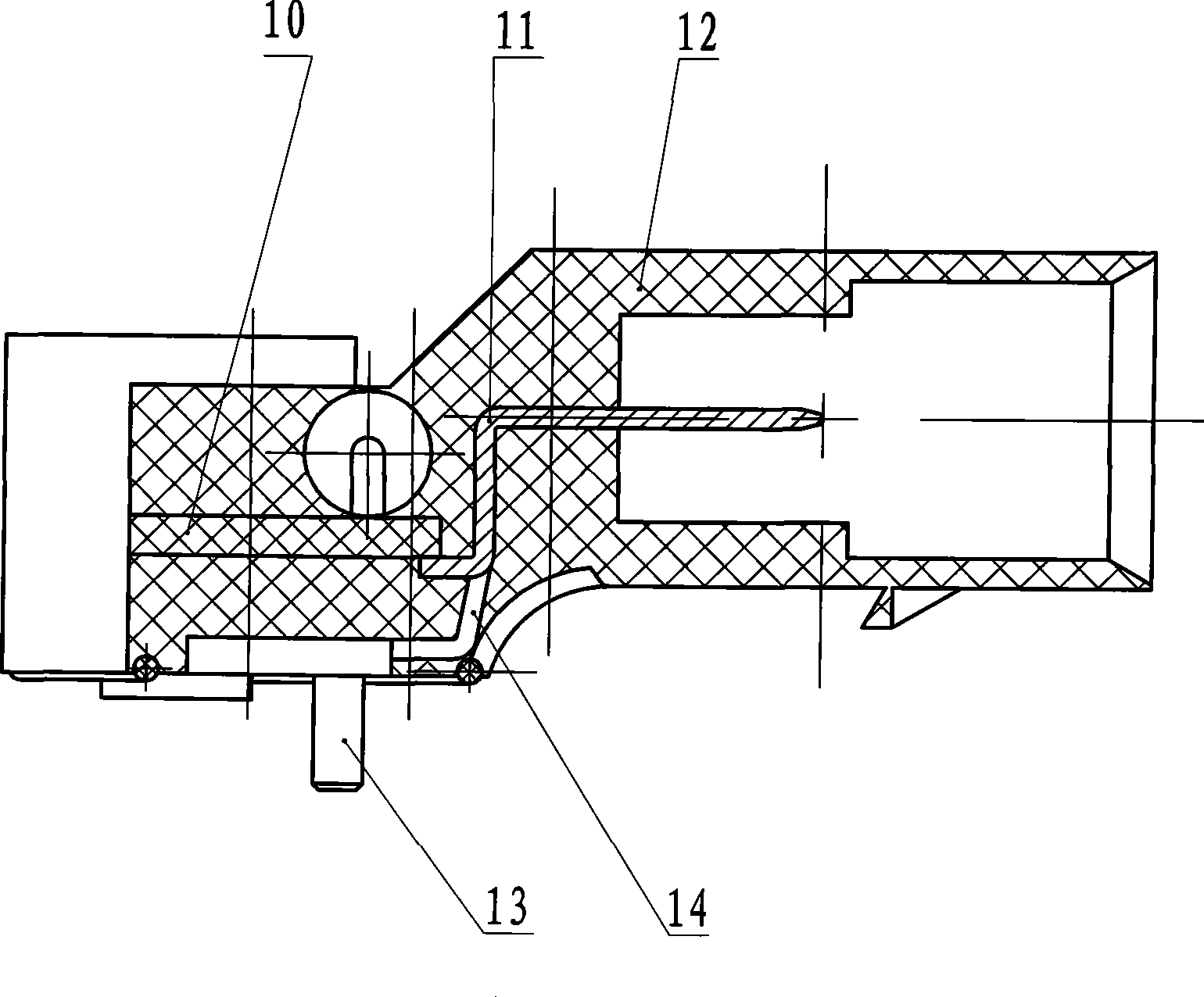
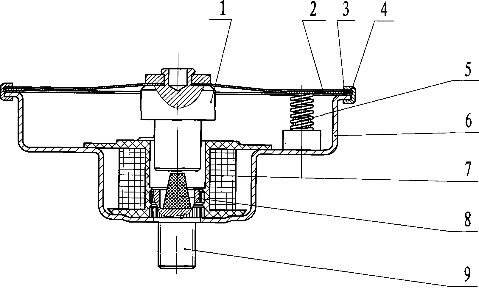
[0020] A new type of electronic horn for vehicles, its composition includes: terminal 15, the circuit board assembly 10 is housed in the described terminal 15, the described circuit board assembly 10 is connected with the electromagnetic coil 7 through the lead wire 13, the described The circuit board assembly 10 is respectively connected with the left insert piece 11 and the right insert piece 14. The outside of the circuit board assembly 10 is covered with a nylon injection molding structure 12, and the negative electrode hole of the terminal post 15 with two holes is connected with the housing 6. The other hole is connected with the electrical lead-out device 5, and the diaphragm 2 is connected with the moving armature 1.
[0021] In the novel vehicle electronic horn, the housing 6 is connected to the static armature 9 with a counterbore, the conductive rubber 8 is housed in the counterbore, and the housing 6 is connected with the The diaphragm 2 of the insulating ring 3 is...
Embodiment 2
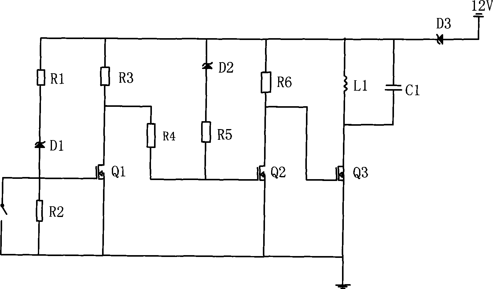
[0024] In this new type of automotive electronic horn terminal, (see attached figure 1 ), which consists of: left insert 11, right insert 14, circuit board assembly 10, two leads 13 and nylon injection molding structure 12. The terminal 15, the circuit board assembly 10 is installed in the terminal 15, wherein the circuit board assembly 10 is first connected with two lead wires, and these two lead wires 13 are respectively connected with the two ends of the electromagnetic coil L1 (7) Wherein the circuit board assembly 10 is connected with the left inserting sheet 11 and the right two inserting sheets 14, so that the circuit board assembly 10 is connected with the power supply. The circuit board assembly 10 after connecting the left insert piece 11 , the right insert piece 14 and the two lead wires 13 is overmolded with nylon material to form a terminal post 15 . The terminal 15 also has two holes, both of which are connected to the signal of the switch S1 of the circuit boar...
Embodiment 3
[0026] In this novel vehicle electronic horn housing 6 assembly, (see attached figure 2 ), its composition includes: electromagnetic coil L1 7, housing 6, static armature 9, conductive rubber 8, moving armature 1, diaphragm 2, insulating ring 3 of diaphragm 2, electrical lead-out device 5. Both ends of the electromagnetic coil L1 7 are respectively connected to the two connected leads of the circuit board assembly. The circuit board assembly is not installed in the casing 6, but installed in the terminal. A counterbore is drilled at the center above the static armature 9, and a conductive rubber 8 is installed in the counterbore. The moving armature 1 and the static armature 9 are connected and disconnected through the conductive rubber 8 . The conductive rubber 8 is connected with the housing 6 through the static armature 9 . The static armature 9 is connected to the housing 6, and the housing 6 is connected to the negative pole of the circuit board assembly, thus realizi...
PUM
 Abstract
Description
Claims
Application Information
 - R&D
- Intellectual Property
- Life Sciences
- Materials
- Tech Scout
- Unparalleled Data Quality
- Higher Quality Content
- 60% Fewer Hallucinations
Browse by: Latest US Patents, China's latest patents, Technical Efficacy Thesaurus, Application Domain, Technology Topic, Popular Technical Reports.
© 2025 PatSnap. All rights reserved.Legal|Privacy policy|Modern Slavery Act Transparency Statement|Sitemap|About US| Contact US: help@patsnap.com


