LED bulb welding machine

A technology of LED light bulbs and welding machines, which is applied in connection, electrical components, circuits, etc., and can solve problems such as the easy burning of solenoid valves

Inactive Publication Date: 2009-08-05
吴志浩
View PDF1 Cites 15 Cited by
  • Summary
  • Abstract
  • Description
  • Claims
  • Application Information

AI Technical Summary

Problems solved by technology

The components on the wire feeding mechanism can successfully complete the wire feeding work, and the wire clamping is reliable; the automatic bubble wire welding device is used to make the welding reliable, with less material, and the coating e

Method used


Image

  • LED bulb welding machine
  • LED bulb welding machine
  • LED bulb welding machine

Examples


Embodiment

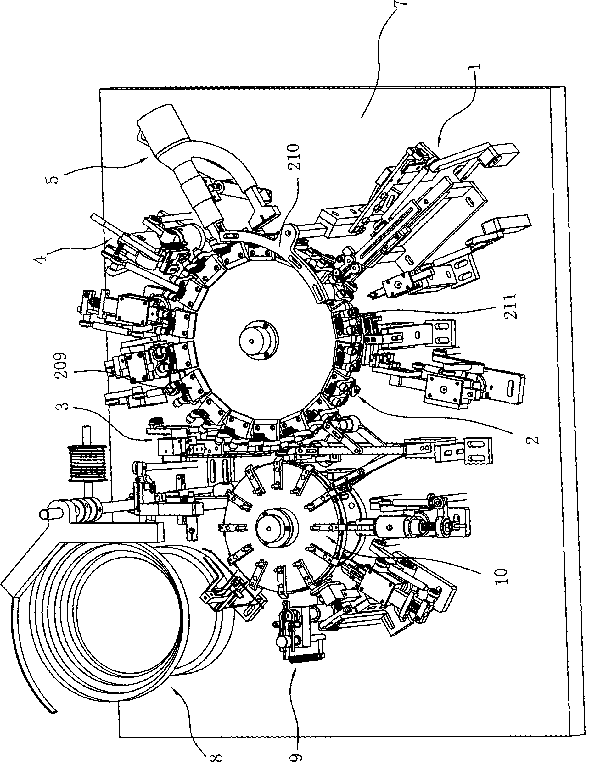
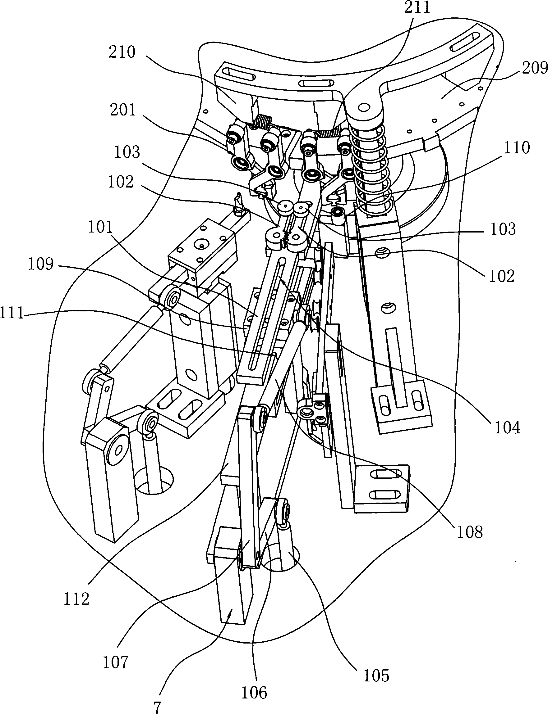
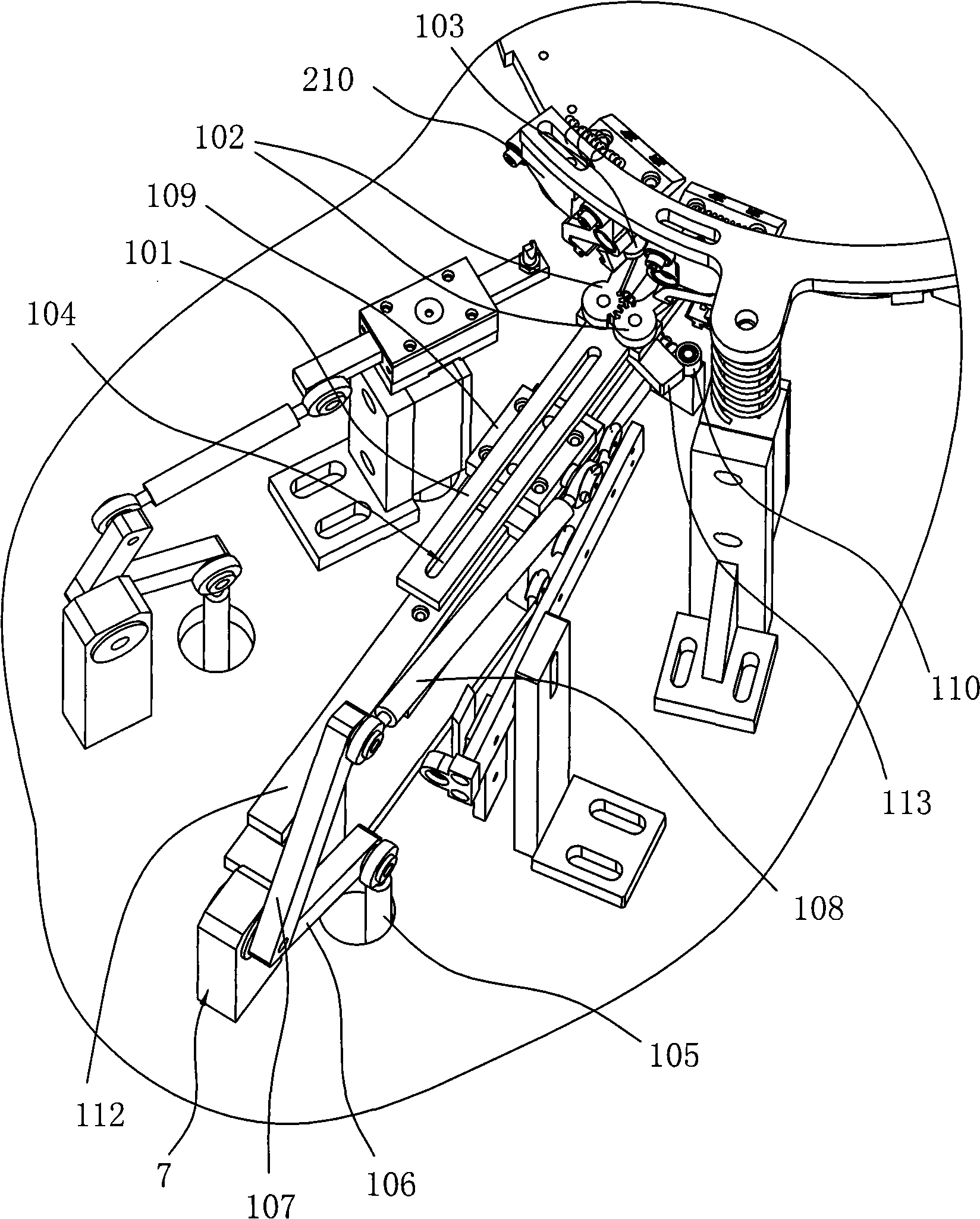
[0081] Example: LED bulb welding machine, such as figure 1 As shown, it includes a frame 7, a power transmission device installed on the frame 7, a bubble feeding device, a wire transmission device and a bubble line connection device that are sequentially provided along the LED bulb welding stroke direction driven by the power transmission device. The bubble delivery device includes a bubble delivery mechanism 8, a bubble foot shaping mechanism 9, and a bubble inspection mechanism that are sequentially provided along the delivery direction of the LED bulb driven by a power transmission device. A wire feeding mechanism, a wire cutting mechanism and a wire stripping mechanism driven by a power transmission device are provided. The bubble wire welding device includes a welding mechanism 3 driven by a power transmission device and a heat-shrinkable tube arranged in sequence along the conveying direction of the LED bulb. mechanism. The wire feeding mechanism includes a wire feedi...


PUM


Abstract

The invention relates to an LED light bulb soldering machine, which comprises a machine frame, a power transmission device, a bulb-delivering device, a transmission wire device and a bulb wire connecting device; wherein, the power transmission device is arranged on the machine frame; the bulb-delivering device, the transmission wire device and the bulb wire connecting device are driven by the power transmission device, and are arranged in sequence along the welding travel direction of the LED light bulbs; the bulb-delivering device comprises a bulb-delivering mechanism, a bulb pin reshaping mechanism and a bulb inspecting mechanism, which are driven by the power transmission device and are arranged in sequence along the delivering direction of the LED light bulbs; the transmission wire device comprises a delivering wire mechanism, a wire-cutting mechanism and a wire stripping mechanism, which are arranged in sequence along the direction of leads, and are driven by the power transmission device; the bulb wire welding wire comprises a welding mechanism and a complete thermal shrinkage pipe mechanism, which are arranged in sequence along the delivering direction of the LED light bulbs and are driven by a force transmission device. The invention has substantial characteristics and remarkable improvements: the transmission wire operates smoothly and accurately; the clamping wire isreliable; the tinning quantity on the wire is uniform and stable; the efficiency of the transmission pipe is high; the coating effect on the plastic pipes is good; and the cylinder is used for controlling the operation of the clutch.

Description

【Technical field】 [0001] The invention relates to an LED bulb soldering machine, in particular to an automatic LED bulb welding machine for connecting an LED bulb with a wire. 【Background technique】 [0002] Festival lanterns need to use a large number of wire segments to connect with a large number of LED lights or rice bulbs to form a string of lights. The off-the-shelf wires on the market are bundled long wires, and the purchased wires need to be cut into wire segments of required length. At present, the mechanisms for processing wire segments on the market usually include a wire feeding assembly and a wire clamping assembly matched with the wire feeding assembly. After the wire segment is processed and shaped, it is also necessary to weld the wire segment and the LED lamp or the rice bulb through a welding mechanism. It is not enough just to be welded together. It is also necessary to put a plastic heat-shrinkable tube on the weld. The usual plastic heat-shrinkable tub...

Claims


Application Information

Patent Timeline
IPC IPC(8): H01R43/02
Inventor 吴志浩
Owner 吴志浩
Why Eureka
Try Eureka