Eureka AIR delivers breakthrough ideas for toughest innovation challenges, trusted by R&D personnel around the world.

Lay-up arrangement and structural arrangement and method for producing a component for aerospace

A structural and structural technology, applied in the field of laminated structures, can solve problems such as time-consuming, high production costs, and positioning errors, and achieve the effects of easy positioning accuracy, cost savings, and cost advantages

Active Publication Date: 2009-08-05
AIRBUS OPERATIONS GMBH
View PDF1 Cites 11 Cited by
  • Summary
  • Abstract
  • Description
  • Claims
  • Application Information

AI Technical Summary

Problems solved by technology

This is very time consuming and requires high labor costs, which results in high production costs for this type of wing shell
The high precision required in the positioning step is also achieved only with difficult manual work, which often leads to positioning errors

Method used


Image

  • Lay-up arrangement and structural arrangement and method for producing a component for aerospace
  • Lay-up arrangement and structural arrangement and method for producing a component for aerospace
  • Lay-up arrangement and structural arrangement and method for producing a component for aerospace

Examples


Embodiment Construction

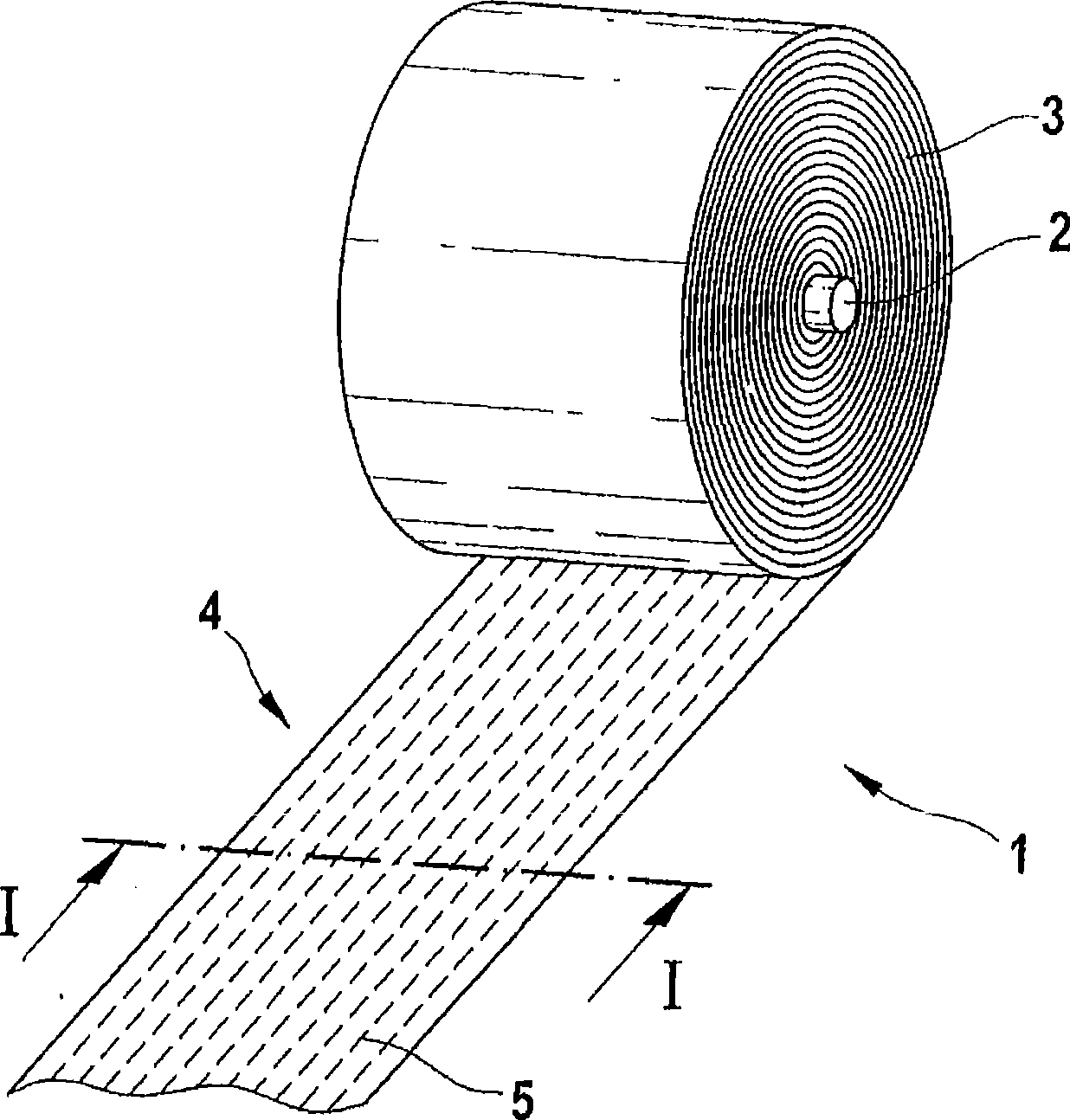
[0041] figure 1 The laminated structure 1 according to the first exemplary embodiment of the present invention is shown in a perspective view.

[0042] The laminated structure 1 is provided in the form of a bundle 3 coiled around a mandrel 2 . The fabric-like end that has been unfolded is indicated with reference numeral 4 . The broken lines schematically show the fiber directions of the glass fibers 5 in the laminated structure 1 . Preferably, the glass fibers 5 extend in the unfolding direction, ie along the fabric-like end 4 .

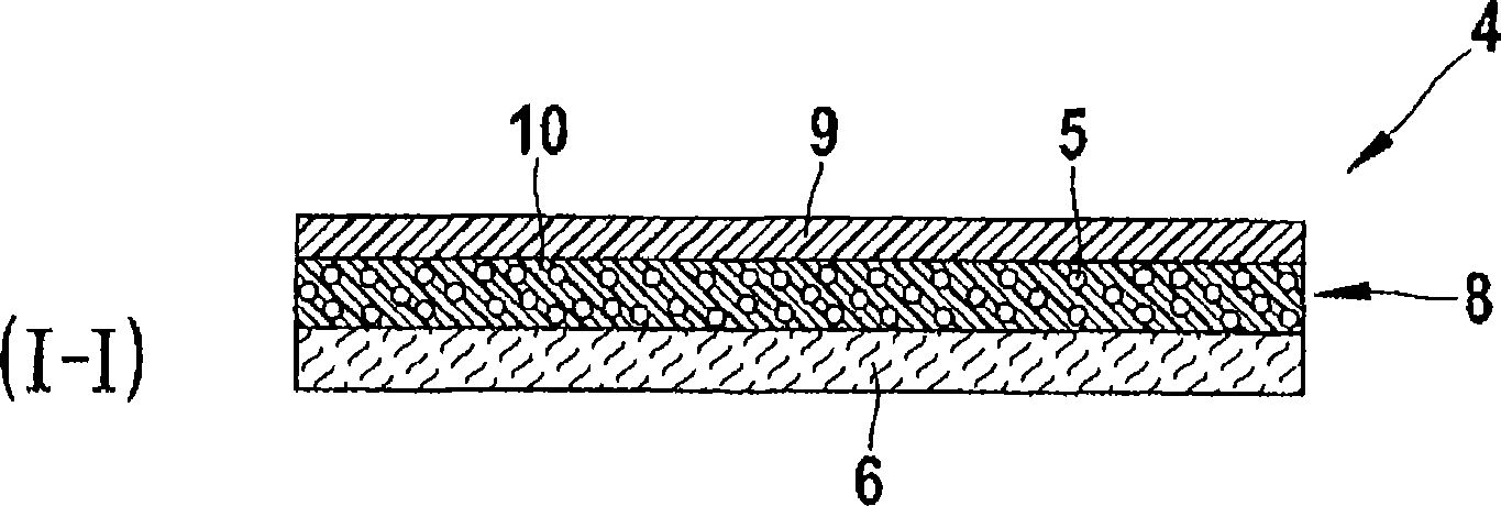
[0043] figure 2 display edge figure 1 Sectional view of the section line I-I in.

[0044] Preferably, the laminated structure 1 comprises a backing layer 6 , a glass fiber laminate 8 and a protective film 9 . Preferably, the backing layer 6 is designed in the form of a paper layer. Arranged on top of the backing layer is a glass fiber layer 5 extending perpendicular to the cross-sectional plane. Located between the glass fibers 5 is a resin...


PUM


Abstract

The invention provides a method for producing a component for aerospace, with the following method steps: supplying a lay-up arrangement (1) to be laid by means of a tape-laying machine (25), with a glass-fibre lay-up (8), which is preimpregnated with a resin matrix, and / or supplying a structural arrangement (12) to be laid by means of a tape-laying machine (25), with a structure (16) which is made of metal and is preimpregnated with a resin matrix, laying the lay-up and / or structural arrangement (1; 12) on a laminating apparatus (23) by means of a tape-laying machine (25), and curing the lay-up and / or structural arrangement (1; 12) and therefore forming the component (37).

Description

technical field [0001] The present invention generally relates to a laminated structure laid up by a tape layer machine, and a build-up structure laid up by a tape layer machine, and methods of manufacturing components for aerospace applications. [0002] Although applicable to any desired aerospace field, the invention and the problem on which it is based will be described in detail with reference to the wing skin of an aircraft. Background technique [0003] In civil aviation, in order to reduce the weight of aircraft, more and more CFRP materials are used to manufacture the entire wing shell. Based on this purpose, one or more layers of CFRP prepreg materials (which can be understood as including carbon fiber laminates pre-impregnated with resin matrix ) formed on another layer. The tape layer machine ensures high-precision positioning of the CFRP prepreg material in the lamination unit. This high-precision positioning is crucial for later performance, in particular fo...

Claims


Application Information

Patent Timeline
Patent Type & Authority Applications(China)
IPC IPC(8): B32B5/28B64D45/02D04H3/004D04H3/04D04H3/045
CPCD04H3/004Y02T50/43Y02T50/433B29C70/885D04H3/045B29C70/386B29C70/545D04H3/04B32B27/04B32B5/28D04H13/00Y02T50/40Y10T156/10Y10T156/1348Y10T156/1788Y10T156/1795Y10T428/31678
Inventor 奥拉夫·洛克尔曼纽尔·荣格索斯腾·布莱克
Owner AIRBUS OPERATIONS GMBH
Why Eureka
Eureka Blog
Learn More