Energy-saving horizontal multi-stage centrifugal pump

A centrifugal pump, horizontal technology, applied in the field of energy-saving horizontal multi-stage centrifugal pumps, can solve problems such as high energy consumption, and achieve the effect of improving efficiency

Inactive Publication Date: 2009-08-12
曹稼昌 +1
View PDF0 Cites 4 Cited by
  • Summary
  • Abstract
  • Description
  • Claims
  • Application Information

AI Technical Summary

Problems solved by technology

[0003] The biggest disadvantage of the traditional horizontal multistage centrifugal pump is that it uses the balance disc 6' to balance the axial force of the pump. It relies on the balance disc 6' to drive the pump shaft to move back and forth to balance the axial force of the pump.
At the same time, 10% to 15% of the high-pressure water in the pump body is lost from the gap of the balance plate, which causes serious problems of high energy consumption in traditional horizontal multistage centrifugal pumps. It cannot be seen outside the body, but it actually exists, and the world's pump theory workers have been studying ways to eliminate this high energy consumption problem, but they have not been able to solve it so far

Method used


Image

  • Energy-saving horizontal multi-stage centrifugal pump
  • Energy-saving horizontal multi-stage centrifugal pump
  • Energy-saving horizontal multi-stage centrifugal pump

Examples


Embodiment Construction

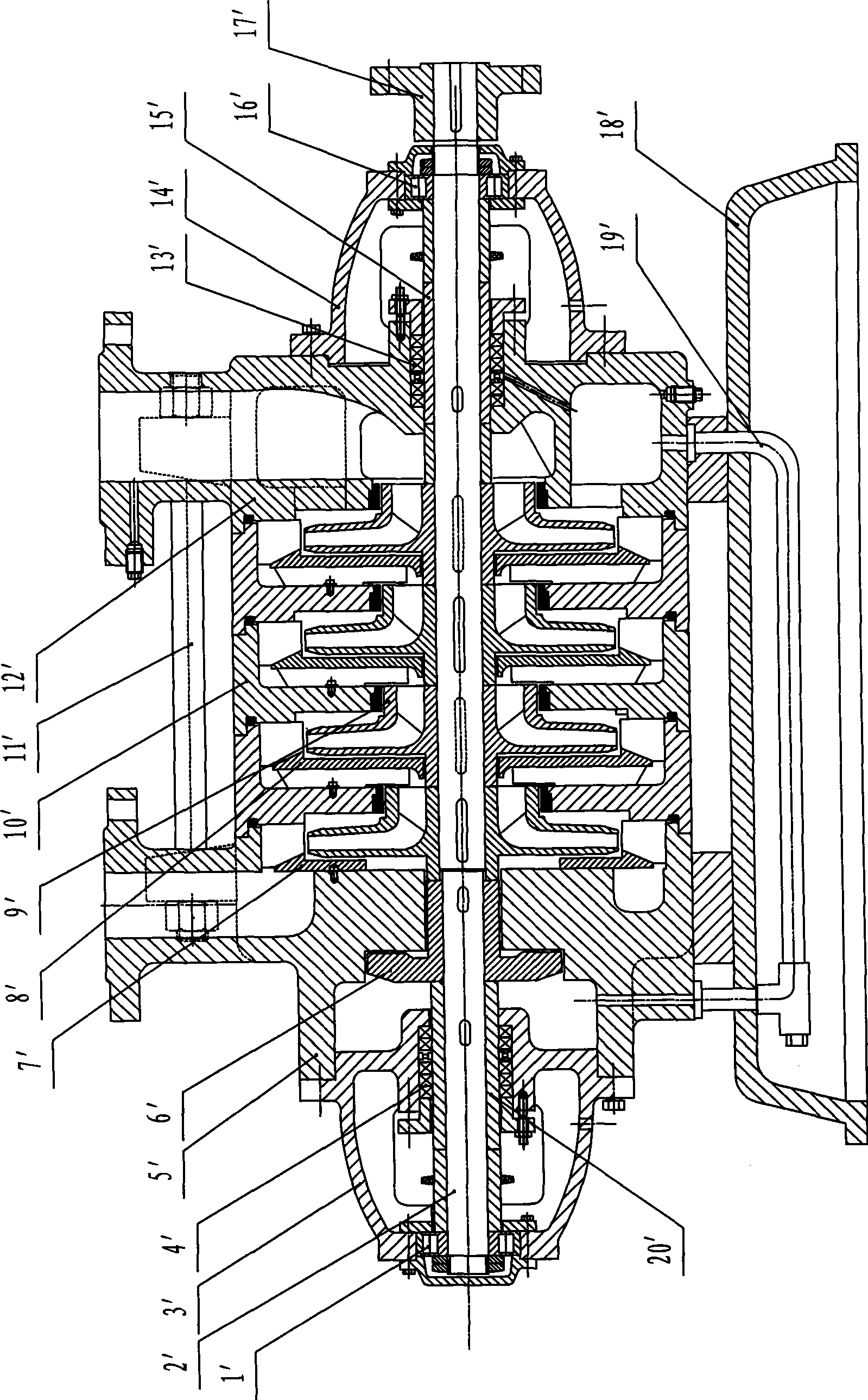
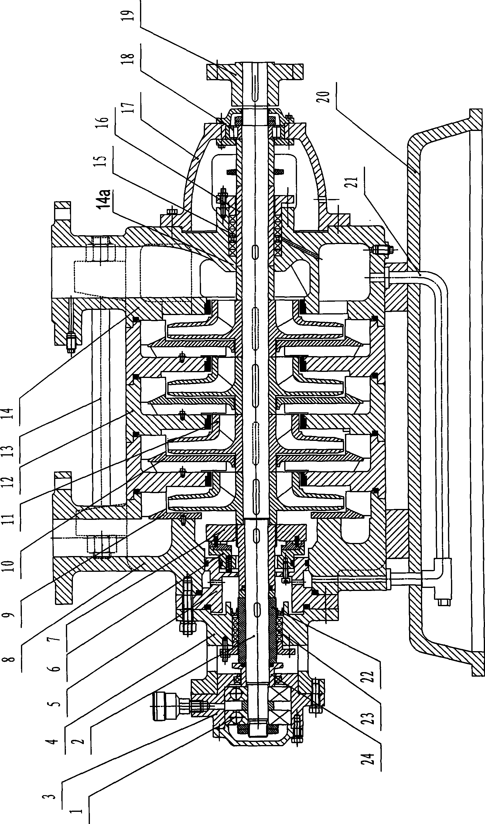
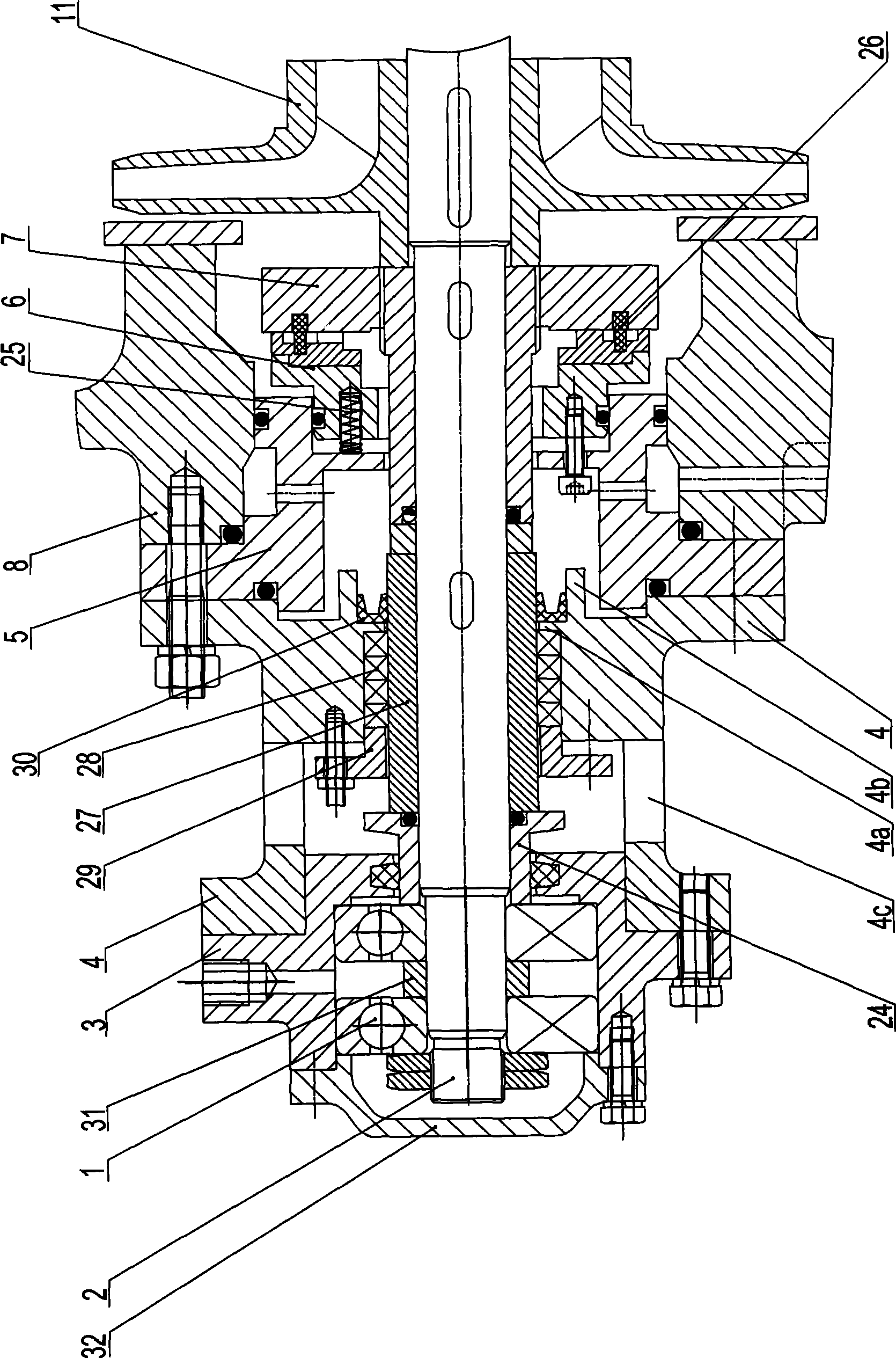
[0015] As shown in the figure: the water outlet casing 8 and the water inlet casing 14 are arranged at intervals on the base 20, and there is a middle casing 12 between the water outlet casing 8 and the water inlet casing 14, and the two bolts 13 are tightened. The ends are respectively arranged on the water outlet shell 8 and the water inlet shell 14, and the water outlet shell 8, the middle shell 12 and the water inlet shell 14 are compressed to form a pump cavity, and the water outlet shell 8 and the water inlet The pump shaft 2 is arranged on the horizontal rotatable frame on the casing 14 of the water section, the impeller 11 and the guide vane 10 are arranged on the pump shaft 2 in the pump chamber, and there is a pump tail sealing device between the casing 14 of the water inlet section and the pump shaft 2, A return pipe 21 is provided on the water outlet casing 8 and the water inlet casing 14, and a disc-shaped pump end seal 4 is fixed on the water outlet casing 8, and ...


PUM


Abstract

The invention relates to a centrifugal pump, in particular to an energy-saving horizontal multistage centrifugal pump. According to the technical proposal provided by the invention, a pedestal is provided with a water outlet section shell and a water inlet section shell at intervals, a middle section shell is arranged between the water outlet section shell and the water inlet section shell, pump shafts are horizontally and rotatablely mounted on the water outlet section shell and the water inlet section shell, a pump shaft in a pump cavity is provided with an impeller and a guide blade, the a pump tail sealing device is arranged between the water inlet section shell and the pump shafts, backwater pipelines are arranged on the water outlet section shell and the water inlet section shell, a discal pump end sealing body is fixed on the water outlet section shell, a pump end balancing body is arranged between the pump end sealing body and the water outlet section shell, a dynamic balancing disc is fixed on the pump shaft between a static balancing disc and the impeller abutting on the water outlet end, the side wall of the dynamic balancing disc facing to the static balancing disc is provided with an annular mounting groove around the pump shaft, and a wearing ring is embedded in the annular mounting groove. The centrifugal pump has good axial force of a balance pump and can eliminate a great deal of reflux loss of high-pressure water, thus the efficiency of the pump is greatly improved.

Description

technical field [0001] The invention relates to a centrifugal pump, in particular to an energy-saving horizontal multistage centrifugal pump. Background technique [0002] The horizontal multistage centrifugal pump has not changed since the invention of the world, so it is called "traditional horizontal multistage centrifugal pump", see figure 1 , it mainly consists of pump end bearing (cylindrical roller bearing) 1', pump shaft 2', pump end bearing bracket 3', pump end packing seal 4', water outlet section 5', balance disc 6', final guide vane 7', guide vane 8', impeller 9', middle section 10', tension bolt 11', water inlet section 12', pump tail packing seal (asbestos packing) 13', pump tail bearing bracket 14', pump tail Shaft sleeve 15', pump tail bearing (cylindrical roller bearing) 16', pump coupling 17', base 18', return water pipeline 19' and pump end shaft sleeve 20', etc. [0003] The biggest disadvantage of the traditional horizontal multistage centrifugal pump ...

Claims


Application Information

Patent Timeline
Patent Type & Authority Applications(China)
IPC IPC(8): F04D1/08F04D29/66
Inventor 曹稼昌曹伟祥
Owner 曹稼昌
Why Eureka
Try Eureka