
Device for separating element device on the circuit board from circuit board matrix

A technology for circuit boards and components, applied in metal processing, metal processing equipment, manufacturing tools, etc., can solve the problems of high energy consumption, loss, and acid consumption, and achieve energy consumption reduction, strong self-adaptation, and high efficiency. Effect

Active Publication Date: 2010-07-07
江苏润联再生资源科技有限公司
View PDF0 Cites 0 Cited by
  • Summary
  • Abstract
  • Description
  • Claims
  • Application Information

AI Technical Summary

Problems solved by technology

The disadvantage of the manual disassembly method is that the work efficiency is too low, and the lead-tin waste gas pollution during the process of soldering points falling off components is serious; while the lead-tin alloy tinning method uses lead-tin alloy tinning or electric heating wire to heat the soldering point to melt, and then The fallen components are removed by a vibration device, and the lead-tin alloy needs a special device for recycling
[0004] The second is the crushing method, which has the disadvantages of high energy consumption, and the mixing of various materials after the waste circuit board is crushed, which increases the difficulty of subsequent processing, and the recovery efficiency of precious metals is low and the loss is serious.
[0005] The third is direct smelting or acid leaching. The disadvantages of this method are large consumption of acid, low utilization rate of resources, many heavy metal pollutants in waste gas, and serious secondary pollution.

Method used


Image

  • Device for separating element device on the circuit board from circuit board matrix
  • Device for separating element device on the circuit board from circuit board matrix
  • Device for separating element device on the circuit board from circuit board matrix

Examples


Embodiment Construction

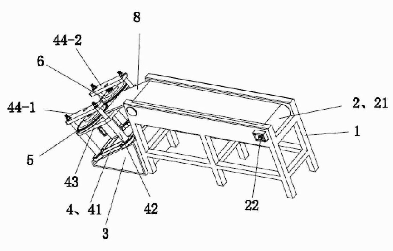
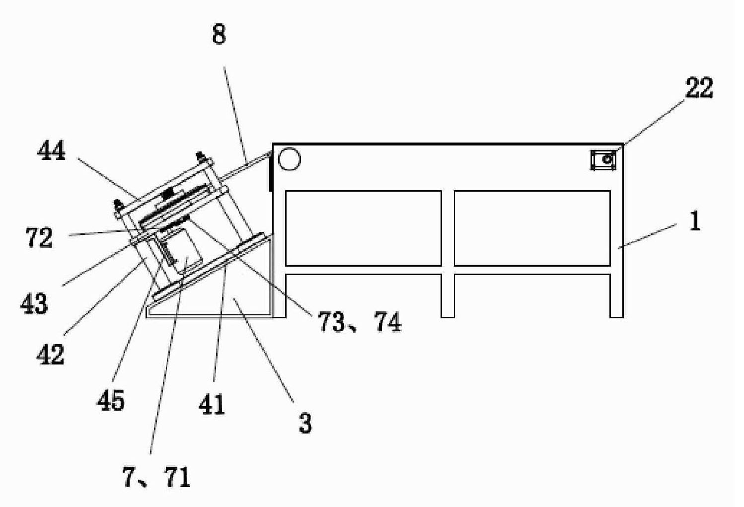
[0032] See figure 1 and figure 2 , the device of the present invention includes a transmission part, a support part, a disassembly part and a guide plate 8 .

[0033] The transmission components include a transmission frame 1 and a transmission belt device 2 . The transmission belt device 2 includes a transmission motor, a motor pulley, a transmission belt, a driven pulley, two transmission shafts and a transmission belt 21 .

[0034] The two transmission shafts are arranged parallel to each other on the upper part of the front and rear ends of the frame 1, and can rotate relative to the frame 1; the specific structure is: the inner ring of a bearing is fixed at the left and right ends of each transmission shaft, and each bearing The outer rings of each are fixed on a corresponding bearing seat, and each bearing seat is fixed at a corresponding position on the upper part of the frame. The conveyor belt 21 is arranged around 2 conveyor shafts.

[0035] The driven pulley is f...


PUM


Abstract

The invention discloses a device for separating components and parts on a circuit board and a substrate of the circuit board, which comprises a transmission part, a support part, a disassembly part and a guide plate, wherein the transmission part comprises a transmission frame and a transmission band device; the support part comprises a lining base and a support frame which comprises a work bed plate, a left upper beam and a right upper beam; the disassembly part comprises a left disk assembly, a right disk assembly and a transmission mechanism; the left disk assembly comprises a left step shaft, a left guide disk, a left dentiform cutter head and a left elastic limit device; the right disk assembly comprises a right step shaft, a right guide disk, a right dentiform cutter head and a right elastic limit device; and the guide plate is arranged between the transmission band of the transmission part and the left guide disk and right guide disk of the disassembly part. The separation device has strong self-adaptation and high efficiency, and simultaneously removes slicker solder in the disassembly process so as not to need heating and smelting the slicker solder again.

Description

technical field [0001] The invention relates to a device for separating components on a circuit board from a base body of the circuit board. Background technique [0002] With my country's modern economic development and technological progress, the electronic information technology industry has become one of the fastest growing industries, and the resulting electronic waste (commonly known as "electronic waste") has grown rapidly. However, electronic waste contains many recyclable non-ferrous metals, ferrous metals, precious metals, plastics and other substances. From the perspective of resource recovery, the potential value is high. The physical pretreatment of waste circuit boards containing electronic components is the first step in the recycling of waste circuit boards. The pretreatment is to effectively separate the electronic components and a small amount of wires in the waste circuit boards from the circuit board substrate. , there are three main methods: [0003] T...

Claims


Application Information

Patent Timeline
Patent Type & Authority Patents(China)
IPC IPC(8): B23P19/04
Inventor 张锁荣周全法朱炳龙王怀栋程洁红
Owner 江苏润联再生资源科技有限公司
Learn More