
Tension control system

A technology of tension control and tension, which is applied in the direction of winding strips, thin material handling, transportation and packaging, etc. It can solve the problems of no visual display of tension values, different tension values ​​at transmission points, and broken main drive shafts, etc., to achieve automation The degree of stability and reliability, reliable performance, and easy maintenance

Inactive Publication Date: 2009-08-19
GUANGXI HEZHOU GUIDONG ELECTRONICS TECH
View PDF0 Cites 17 Cited by
  • Summary
  • Abstract
  • Description
  • Claims
  • Application Information

AI Technical Summary

Problems solved by technology

[0003] In short, the frequent problems of the old worm gear transmission method are: the main transmission shaft is broken, the friction plate for adjusting the tension is easy to fail, the worm gear is worn, the tension value of each transmission point is different, and there is no visual display of the tension value. It is also difficult to ensure uniform tension at each point, and the worm gear and worm often need to be maintained with lubricating oil

Method used


Image

  • Tension control system
  • Tension control system

Examples


Embodiment Construction

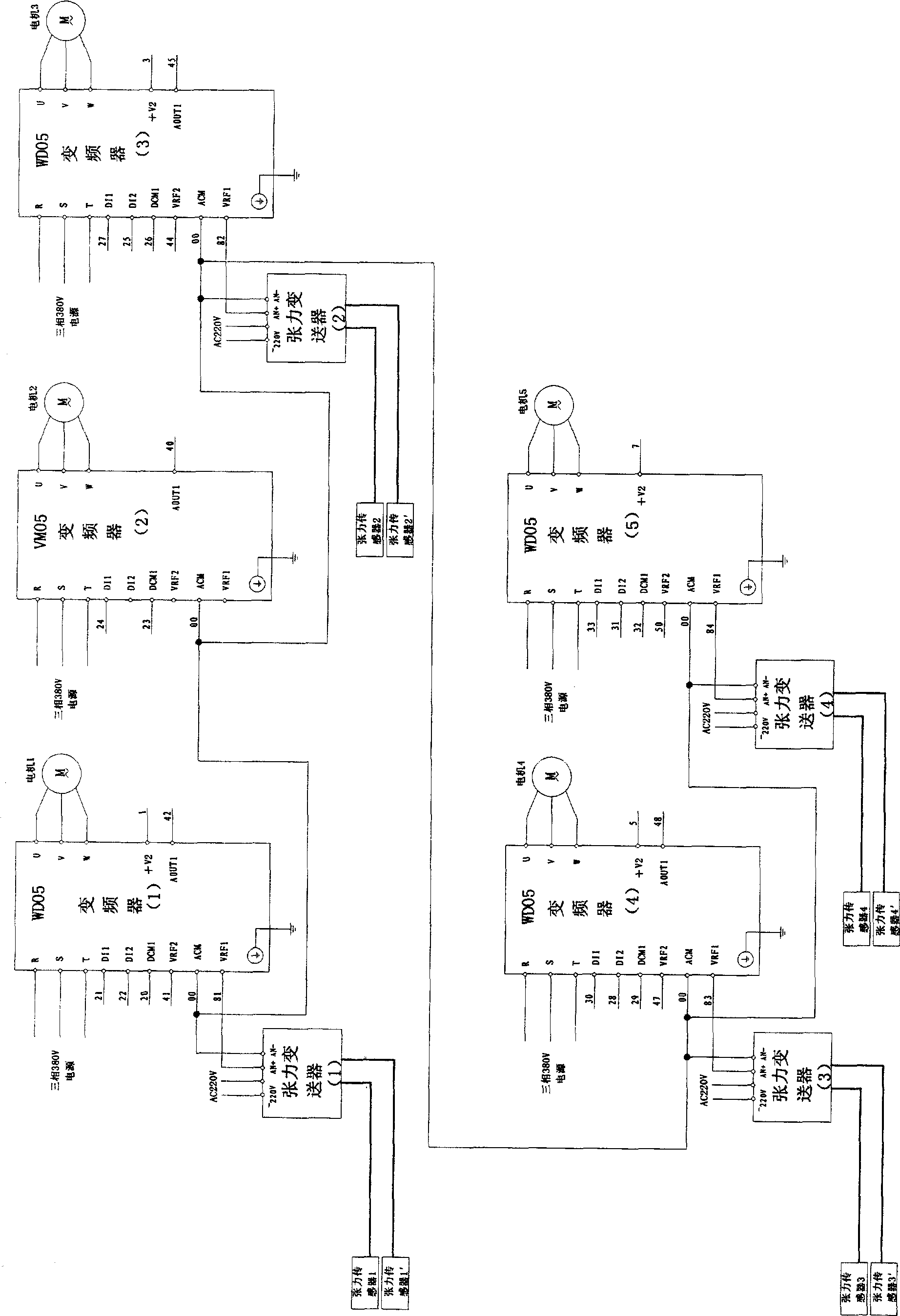
[0019] refer to figure 1 , except that the present invention has a copper conductive roller each in the foil releasing device 1 and the foil receiving device 24, 27 rollers are also arranged at various positions of the entire walking foil, wherein five driving rollers are respectively arranged on the 4th, 8th, 4th, 8th, The positions of 12, 18, and 24 are copper rollers, and the remaining 22 rollers are PP rollers, the driving roller is a copper roller, the driven roller is a PP roller, and the driving roller and the driven roller are connected by sprockets. Four tension sensors 2, 3, 4, and 5 are placed on driven rollers 6, 10, 16, and 22, and the tail ends of the five driving rollers are respectively connected to three-phase asynchronous motors + reducer kits 6, 7, and 8 , 9, 10, four transmitters 11, 12, 13, 14 are connected to four tension sensors 2, 3, 4, 5, four transmitters 11, 12, 13, 14 and four sets of three-phase Motor+reducer kits 6, 8, 9, and 10 are connected to ...


PUM


Abstract

The invention discloses a tension control system, which comprises a driving roller, a driven roller and a tension adjusting device, and is characterized in that in a closed-loop full automatic tension control system formed by a tension sensor on a position of a film, a tension converter, a special winding frequency converter, an electric motor, the driving roller, a group of driven rollers and the tension sensor on the position of the film; the tension sensor of the film, the tension converter and the special winding frequency converter are connected through signal wires in turn; the special winding frequency converter is connected with the electric motor through a cable; the electric motor is directly connected to the driving roller; and the driving roller and the driven rollers are connected by chain wheels. The tension control system adopts frequency conversion winding control technology to overcome the defects of the prior transmission mode, the tension on each position of a production line can be displayed intuitively, and the integral tension of the whole line can be adjusted. The tension control system can be widely applied to the transmission control of the production lines for processing aluminum foils, films, textiles, printing, plastics, and the like.

Description

technical field [0001] The invention relates to a tension control system, in particular to a tension control system for moving, driving or winding thin objects such as films during the production process, especially a foil tension control system for the aluminum foil production process. Background technique [0002] The production process of electronic aluminum foil requires relatively stable tension to produce good products. The problem of stable tension control has always plagued the aluminum foil production industry. The current transmission mode in production is: driven by a main shaft, each transmission point drives each roller to operate with a worm gear structure, and the tension of the roller is adjusted by the tension friction plate that is squeezed and connected with the roller shaft. In this transmission mode, the mechanical loss of the main shaft and the speed difference control mechanism is large, and it is difficult to perform speed control and tension control ...

Claims


Application Information

Patent Timeline
Patent Type & Authority Applications(China)
IPC IPC(8): B65H23/198B65H23/18
Inventor 杨小飞刘国滔胡知健
Owner GUANGXI HEZHOU GUIDONG ELECTRONICS TECH
Learn More