High-dipping ore block house column mining method

A mining method and steep inclination technology, which are applied in the field of mining steeply inclined ore bodies, can solve the problems that it is difficult for operators to reach the site where there is no work on the working surface, ventilation, blocking of pedestrian and wind flow passages, and high ore loss rate, etc. Achieve the effect of good ventilation, improved working environment and high ore recovery rate

Inactive Publication Date: 2009-08-19
KUNMING IRON & STEEL GRP CO LTD
View PDF0 Cites 20 Cited by
  • Summary
  • Abstract
  • Description
  • Claims
  • Application Information

AI Technical Summary

Problems solved by technology

Because when mining the ore body with steep slope and below medium thickness, the ore pillar is high and the ore loss rate is high. The mined ore slides down the steep mine wall and blocks the pedestrian and air flow passages. , ventilation and other conditions
The existing room-and-pillar method is only suitable for the mining of gently inclined or horizontal ore bodies

Method used


Image

  • High-dipping ore block house column mining method

Examples


Embodiment 1

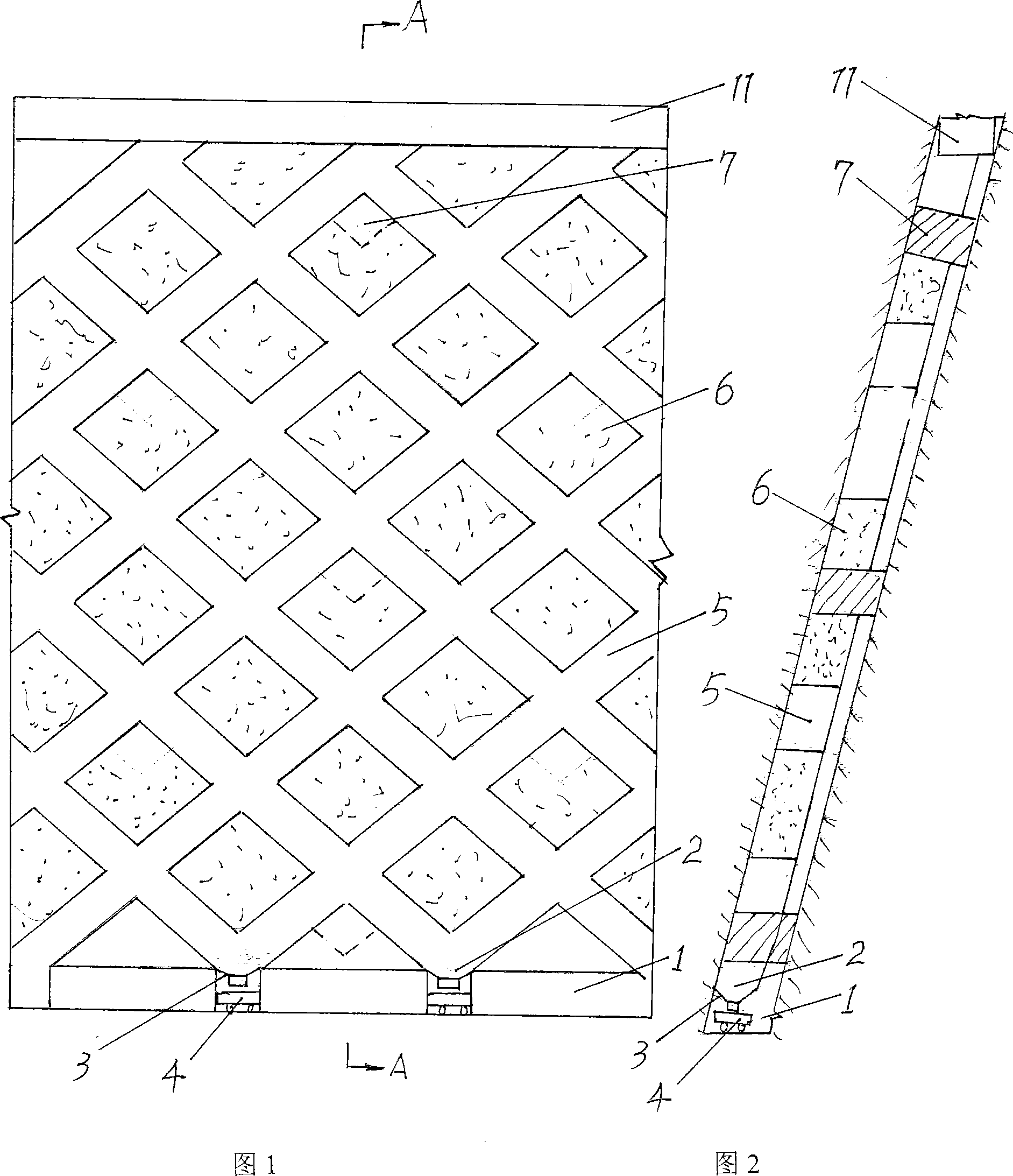
[0020] A. At the bottom of the steeply inclined ore body, excavate a transport roadway 1 along the direction of the ore body. The roadway is 2.5 meters wide and 2 meters high, and is used to export ore and serve as a pedestrian passage and wind flow passage;

[0021] B. In the transportation roadway 1, excavate the ore-feeding groove 2 every 10 meters, install the ore-drawing funnel 3 on the groove 2, place the mine car 4 under the funnel 3, and place the ore-falling groove 2 on the ore-falling groove 2. Trough 2 is the intersection point, and two inclined shafts 5 are excavated uphill to the top of the stope. Each inclined shaft forms a 45° angle with the horizontal line, and the width of the inclined shaft is about 3 meters. During the excavation, rock drilling and explosive blasting are used. Carry out; the mined ore slides by its own weight along the inclined shaft 5 to the ore-drawing funnel at the intersection point, and then puts it into the mine car 4 in the transportat...

Embodiment 2

[0025] A. On the steeply inclined ore body, excavate the transport roadway 1 along the direction of the ore body. The roadway is 2.2 meters high and 2 meters high, which is used to export ore and serve as a pedestrian passage and ventilation passage;

[0026] B. In the transportation roadway 1, excavate the ore falling groove 2 every 10 meters, install the ore funnel 3 on the groove 2, place the mine car 4 under the funnel 3, and use the ore falling groove 2 on the ore falling groove 2 2 is the intersection point, and two inclined shafts 5 are excavated uphill to the top of the stope. Each inclined shaft forms a 43° angle with the horizontal line, and the width of the inclined shaft is 3 meters. During the excavation, rock drilling and explosive blasting are used. The mined ore slips by its own weight along the inclined shaft 5 to the ore-feeding groove 2 at the intersection point, and then falls into the mine car 4 in the transportation roadway 1 through the funnel 3 and is se...


PUM


Abstract

The invention provides a steeply inclined ore body room-and-pillar mining method, comprising the following steps: a traveling roadway is tunneled along the trend of the ore body; broken-ore troughs are tunneled in the traveling roadway at interval with the broken-ore troughs as junctions, two inclined shafts are tunneled toward the uphill direction to the top of a quarry; a rhombic ore block formed between the inclined shafts is mined from top to bottom in sequence; ore pillars are left in the rhombic ore block at interval; ores mined in the process of tunneling slip into the broken-ore troughs along the inclined shafts depending on self weight and then put into a mine car in the traveling roadway from the broken-ore troughs to be delivered; the tunneled inclined shafts in networked cross distribution can serve as a passage and an ore chute for the miners to go up and down and as a ventilation shaft and a workplace for rock drilling, ore breaking and blasting avoiding. The method is good in ventilation effect, safe, reliable, low in cost, simple in construction operation, high in ore recovery ratio and low in dilution ratio.

Description

technical field [0001] The invention relates to a mining method, in particular to a method for mining steeply inclined ore bodies, and belongs to the technical field of mining. Background technique [0002] Occurrence conditions of ore bodies are often different due to different mines or even the same mine but in different ore bodies. Therefore, it is objectively required to adopt different methods for mining different ore bodies, so a wide variety of mining methods have been formed. . At present, there are many classifications of mining methods at home and abroad, and the academic disputes are relatively large, but it is generally recognized that they are divided into three categories according to the ground pressure management methods during mining: empty field method, filling method and caving method. Among them, the filling method is suitable for mining deeply buried ore bodies (such as more than 800mm), or there are important projects on the surface such as roads, rail...

Claims


Application Information

Patent Timeline
Patent Type & Authority Applications(China)
IPC IPC(8): E21C41/00
Inventor 邱崇栋
Owner KUNMING IRON & STEEL GRP CO LTD
Why Eureka
Try Eureka