Special-shaped microchannel and exterior corrugated fin integration molding heat exchanger

A technology of corrugated fins and microchannels, which is applied in the field of heat exchangers in which special-shaped microchannels and outer corrugated fins are integrally formed, can solve the high requirements for stability and reliability, reduce system stability and reliability, and solder thickness Uneven sand holes and other problems, to achieve the effect of eliminating contact thermal resistance, reducing volume and weight, and enhancing convective heat transfer

Inactive Publication Date: 2009-08-19
SOUTH CHINA UNIV OF TECH
View PDF0 Cites 19 Cited by
  • Summary
  • Abstract
  • Description
  • Claims
  • Application Information

AI Technical Summary

Problems solved by technology

Because high-pressure gas is easy to leak (even a slight leak will cause the performance of the whole machine to decline after long-term operation), therefore, the design of the carbon dioxide heat exchanger must consider strict high-pressure sealing requirements, and welding process cannot be accepted.
The design of traditional air-conditioning heat exchangers generally adopts welding technology, which is prone to uneven solder thickness and unavoidable sand holes in the welding parts, forming stress concentration points and corrosion breakthrough points, which reduces the stability and reliability of the system
Due to the high pressure of the refrigerant system, the requirements for stability and reliability are also higher than those of traditional refrigerants, and the welding process is basically unacceptable

Method used


Image

  • Special-shaped microchannel and exterior corrugated fin integration molding heat exchanger
  • Special-shaped microchannel and exterior corrugated fin integration molding heat exchanger
  • Special-shaped microchannel and exterior corrugated fin integration molding heat exchanger

Examples


Embodiment Construction

[0028] The present invention will be further described below in conjunction with the accompanying drawings and examples. It should be noted that the protection scope of the present invention is not limited to the scope described in the embodiments.

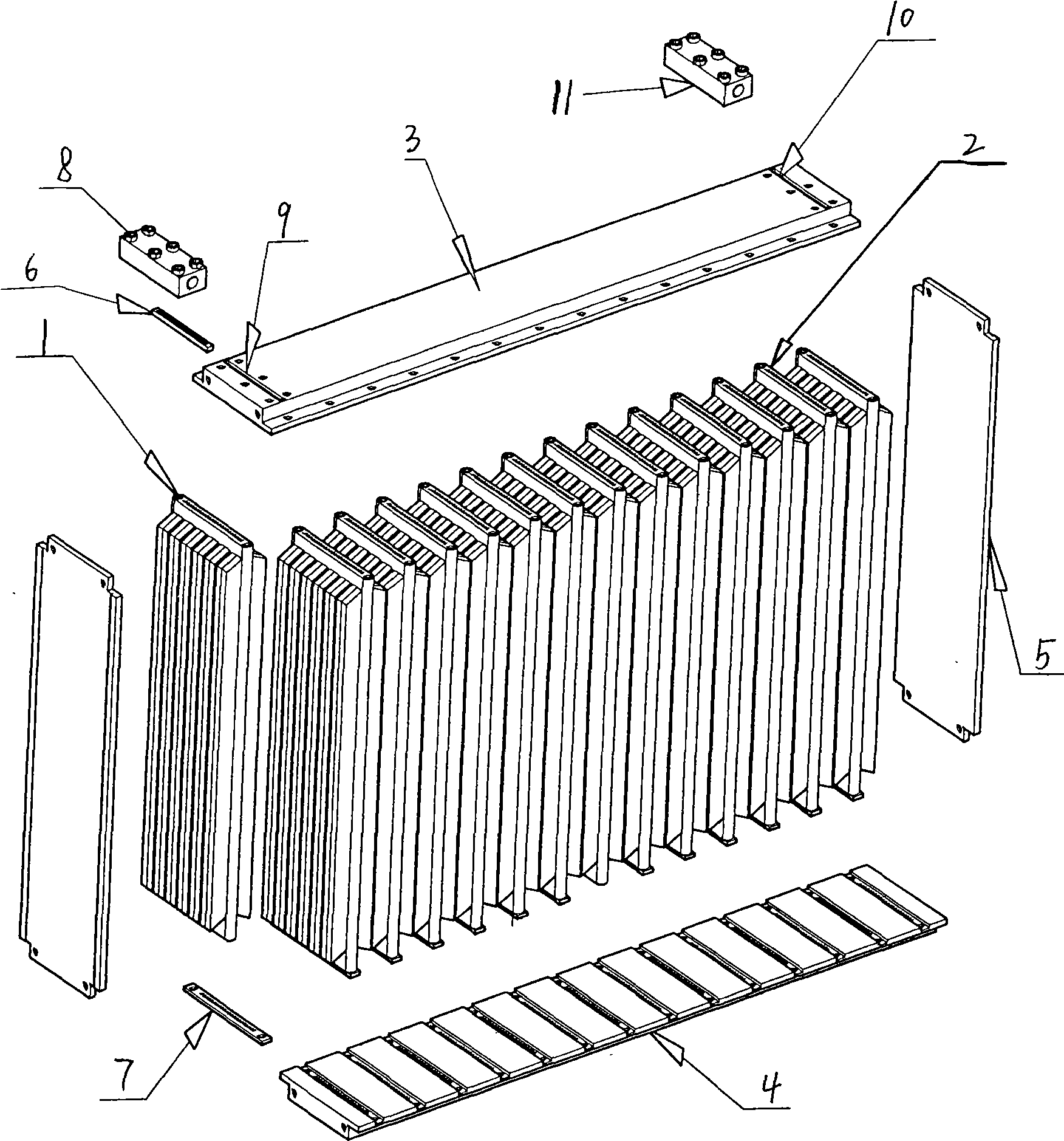
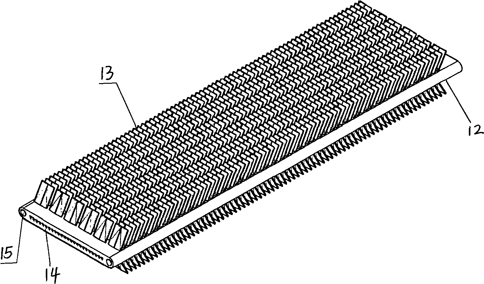
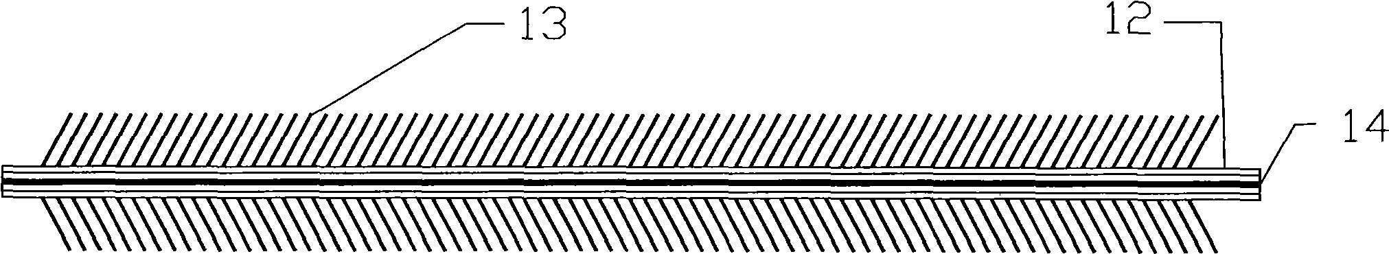
[0029] Such as Figure 1-7 As shown, a heat exchanger in which special-shaped microchannels and outer corrugated fins are integrally formed includes a heat sink group 2, an upper cover plate 3, a lower cover plate 4, a side plate 5, an air inlet 9 and an air outlet 10; Group 2 is formed by connecting a plurality of cooling fins 1 side by side, and is located in a frame structure with openings on both sides composed of the upper cover plate 3, the lower cover plate 4 and the side plate 5. One side of the opening faces the hot side, and the other side To be equipped with a blowing device, the upper cover 3 and the lower cover 4 are connected to the upper and lower ends of the heat sink by screws, and there are silicone gaskets betwe...


PUM


Abstract

The invention discloses a heat exchanger integrally formed by a profiled micro-channel and an external corrugated fin. The heat exchanger comprises a fin group, an upper cover plate, a lower cover plate, a side plate, an air inlet and an air outlet; the fin group is connected in parallel by a plurality of fins; each fin is made of plate material; two sides of the fin is provided with a corrugated fin and the middle part of the fin is provided with a plurality of profiled micro-passage structures; the corrugated fin and the plate material are integrally formed; the upper cover plate and the lower cover plate are respectively provided with a trough which is used for arranging the fin; two adjacent troughs of the upper cover plate and the lower cover plate are communicated with each other intermittently, thus leading the refrigerant to flow through a plurality of fins sequentially; and the profiled micro-passage is a square passage with the side length of 0.8-1mm. The heat exchanger utilizes the micro-pore passage technology, integral external fin technology and no-welding refrigerant high-pressure sealing technology, is applicable to CO2 refrigeration systems, and effectively solves the problem of the high-pressure running of the system. The heat exchanger has compact structure, high heat-exchanging efficiency, small volume, light weight, is made of full-aluminium composite, and greatly reduces the cost.

Description

technical field [0001] The invention relates to a heat exchanger, in particular to an energy-saving, environment-friendly, low-cost heat exchanger in which special-shaped microchannels and outer corrugated fins are integrally formed. technical background [0002] With the increasing shortage of energy, energy saving work is becoming more and more important. How to improve the energy efficiency ratio of household air conditioners has become a top priority for air conditioner manufacturers. In today's highly competitive market, whether air conditioners with low cost and high energy efficiency ratio can be produced is related to the life and death of enterprises. The heat exchanger is an important component of the air conditioner. The scientific research institutions of various enterprises are committed to improving the heat exchanger or proposing a new type of heat exchanger, which has achieved the purpose of improving energy efficiency and reducing costs. [0003] Studies h...

Claims


Application Information

Patent Timeline
Patent Type & Authority Applications(China)
IPC IPC(8): F28D1/03F28F3/08F28F3/12F28F3/10F28F21/08
Inventor 汪双凤李炅
Owner SOUTH CHINA UNIV OF TECH
Why Eureka
Try Eureka