
Force sensor and air measurement method thereof

A technology of force sensor and wind speed, which is applied in the field of force sensor and its wind speed measurement, can solve the problems of ultrasonic sensor measurement accuracy, can not be used to measure high-speed wind, high manufacturing and installation requirements, and achieve multi-phase accurate measurement, effective and sensitive One-way force, fast response effect

Inactive Publication Date: 2009-08-19
SOUTHEAST UNIV
View PDF0 Cites 25 Cited by
  • Summary
  • Abstract
  • Description
  • Claims
  • Application Information

AI Technical Summary

Problems solved by technology

Pitot tube anemometer is a typical dynamic pressure anemometer. This kind of equipment has simple structure, good adaptability to the environment, high accuracy and resolution, but it is not suitable for low-speed wind measurement; mechanical anemometer The structure is simple, and the wind speed and wind direction can be sensed at the same time by using the rotor blade probe, but the manufacturing and installation requirements are high, and there will inevitably be wear and aging problems during long-term use, which will affect the measurement accuracy, and it is not suitable for harsh weather conditions. work; the thermal differential anemometer measures the wind speed by using the wind speed to affect the cooling speed of the heating sensitive element. Due to its easy integration, it is a popular research method in the field of wind speed measurement. At present, this type of instrument has a small range and cannot It is used to measure high-speed wind, which is greatly affected by humidity and cannot be used in large areas. In recent years, based on the influence of wind speed on the propagation speed of ultrasonic waves, an ultrasonic anemometer has been proposed, but the sound speed is obviously affected by environmental factors. Atmospheric humidity, temperature And factors such as the concentration of impurities contained in it will affect the measurement accuracy of the ultrasonic sensor
[0004]The current anemometer is restricted by factors such as structure, principle, and range, and has the problem of poor versatility, especially not suitable for long-term unattended in the field automatic weather station

Method used


Image

  • Force sensor and air measurement method thereof
  • Force sensor and air measurement method thereof
  • Force sensor and air measurement method thereof

Examples


Embodiment Construction

[0021] Below in conjunction with accompanying drawing, the technical scheme of invention is described in detail:

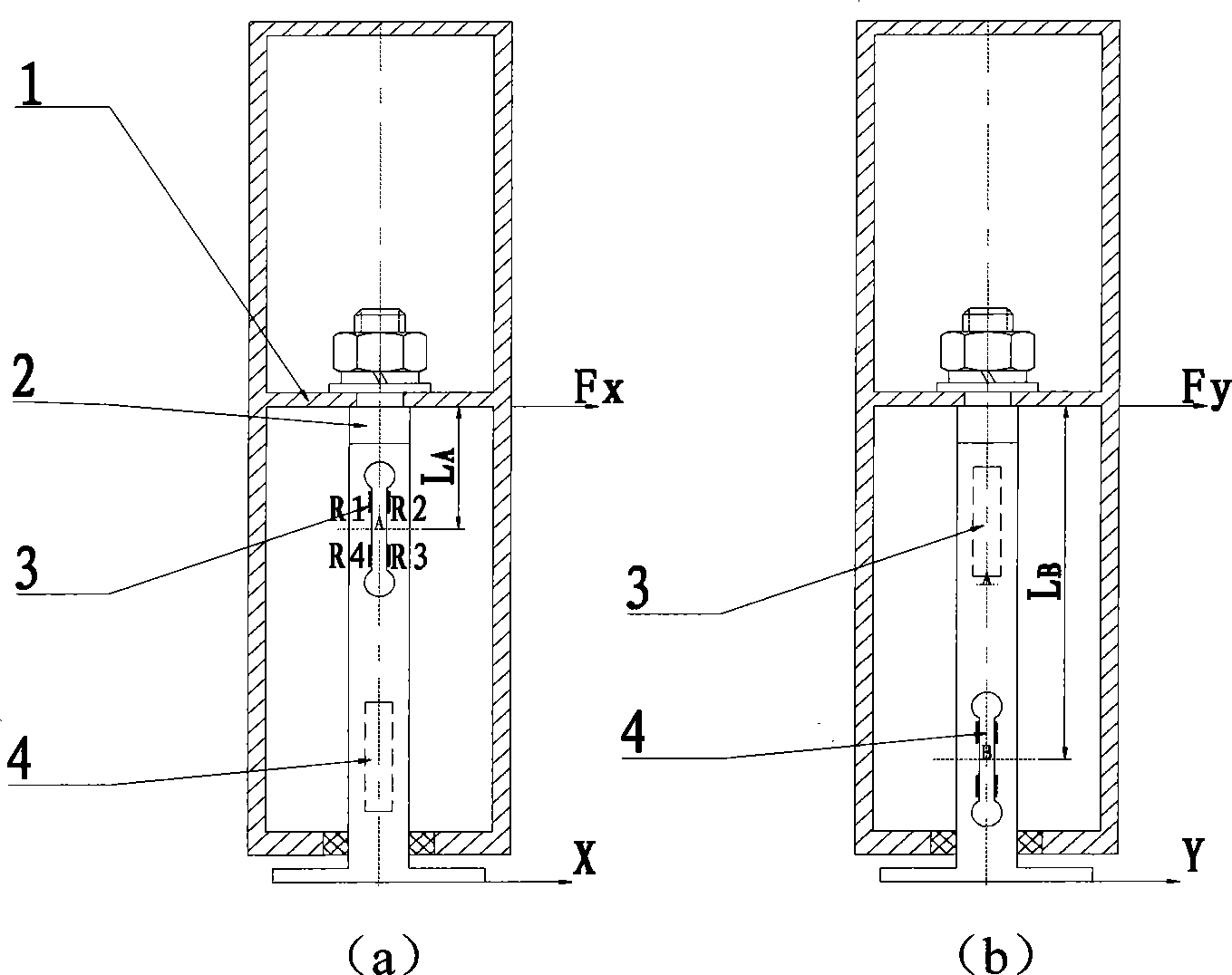
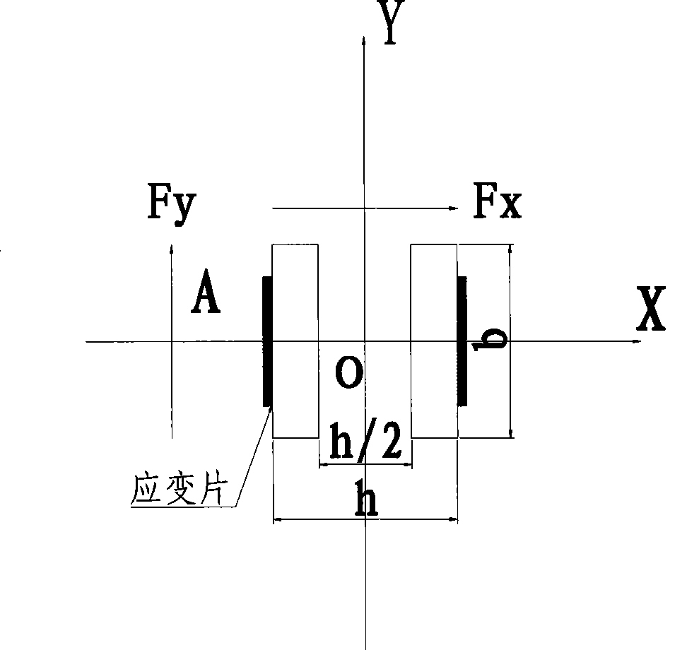
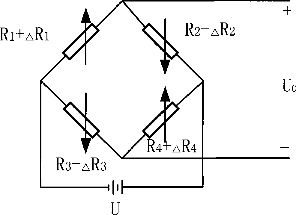
[0022] Such as figure 1 As shown, 1 is a wind-receiving body with a circular section, which converts the wind pressure into the load of the two-dimensional force sensor. 2 is an elastic beam, which is essentially a combination of two orthogonal elastic strain beams. The elastic beams are respectively opened with upper and lower grooves A and B to increase the sensitivity of the sensor. A set of strain gauges 3 and 4 are attached to both sides of the elastic beam to form a Wheatstone differential full-bridge measurement circuit, which can measure the strain in the X and Y directions of the elastic beam respectively, thereby measuring the wind load F of the elastic beam . Among them, the upper sensor A is used to measure the force F in the X direction x , the lower sensor B is used to measure the force F in the Y direction y .

[0023] Such as figure 2 As sho...


PUM


Abstract

The invention discloses a force sensor and a wind speed measuring method thereof. The force sensor includes a wind-engaging body, an elastic beam, a first strain gauge group and a second strain gauge group. The measuring method adopts the strain gauges to measure the wind load of the elastic beam and obtains wind speed and direction through measurement. Without moving elements, the invention has quick response, simple and reliable structure and strong environment applicability.

Description

technical field [0001] The invention relates to a sensor and a measuring method thereof, in particular to a force sensor and a wind speed measuring method thereof. Background technique [0002] In meteorology, environmental protection, industrial and agricultural production, construction, military and many other fields, air velocity is an important detection parameter. In particular, the rapid development of automatic weather stations in recent years has put forward higher requirements for wind speed measuring instruments. It is of great significance to develop wind speed measuring instruments that can adapt to harsh weather conditions and realize multi-point, multi-phase, and instantaneous accuracy. [0003] At present, there are many kinds of instruments and equipment used to measure wind speed, usually based on the following principles: dynamic pressure type, mechanical type, thermal type, ultrasonic type, digital type, etc. Pitot tube anemometer is a typical dynamic pre...

Claims


Application Information

Patent Timeline
IPC IPC(8): G01L9/04G01P5/02G01P13/02
Inventor 崔建伟宋爱国许茜茜
Owner SOUTHEAST UNIV
Learn More