Synchronous switch

A synchronous switch and contact technology, used in reactive power compensation, reactive power adjustment/elimination/compensation, etc., can solve problems such as high cost, reduced reliability, and large conduction loss of thyristors

Inactive Publication Date: 2009-08-19
王家强
View PDF0 Cites 17 Cited by
  • Summary
  • Abstract
  • Description
  • Claims
  • Application Information

AI Technical Summary

Problems solved by technology

The use of AC contactors will cause inrush current when the capacitor is switched on, and the use of thyristors will cause a large conduction loss. The method of using thyristors in

Method used


Image

  • Synchronous switch

Examples


Example Embodiment

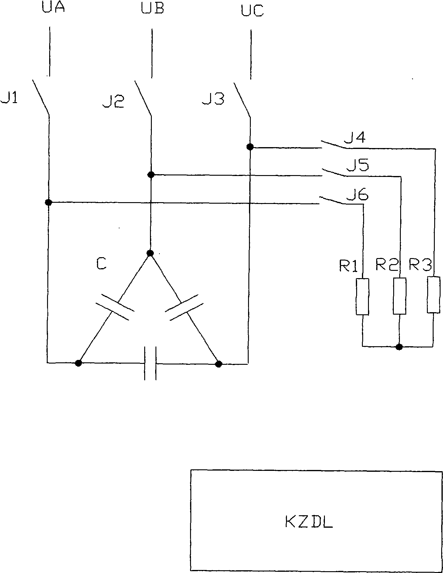
[0016] Combine below figure 1 Describe a specific implementation of the present invention:

[0017] When the capacitor is put in, the control circuit first measures the zero-crossing point of the AC phase line voltage. If the closing action time of the magnetic latching relay is 5 milliseconds, the closed driving signal of J1 and J3 will be sent out 5 milliseconds after the zero-crossing point is measured, so J1 The contact with J3 is closed at the next zero crossing of the AC phase line voltage. Then 5 milliseconds after the zero-crossing point of the B-phase voltage, the J2 closing drive signal is sent out, so the J2 contact is closed at the zero-crossing point under the B-phase phase voltage. This is the synchronous operation when the capacitor is put in, so as to achieve no inrush current of the capacitor. Invest.

[0018] When the capacitor is cut off, the control circuit first measures the zero-crossing point of the B-phase voltage. If the disconnection time of the magnetic ...


PUM


Abstract

The invention relates to a capacitor fling-cut switch with simple structure, low cost and high reliability and no inrush current when switching capacitors. The capacitor fling-cut switch comprises three magnetic latching relays (J1, J2, and J3) and corresponding control circuits which can control a three-phase power capacitor C. The input terminal of a connection point of J1 is connected with an A phase power supply and the output terminal of the connection point of J1 is connected with a first terminal of the capacitor C; the input terminal of a connection point of J2 is connected with a B phase power supply and the output terminal of the connection point of J2 is connected with a second terminal of the capacitor C; the input terminal of a connection point of J3 is connected with a C phase power supply and the output terminal of the connection point of J3 is connected with a third terminal of the capacitor C. The make-and-break operations of connection points of the magnetic latching relays are controlled by the control circuits; the make-and-break operations of connection points of all magnetic latching relays are always related closely with the phases of power supplies, therefore the capacitor fling-cut switch belongs to synchronous switches and the no inrush current input and current zero-crossing cut-off of the capacitor can be realized by using the functions of the synchronous switch.

Description

Technical field: [0001] The invention relates to a reactive power compensation device (also known as a power factor compensation device) for compensating reactive current in a power system, in particular to a switching control method of capacitors in the reactive power compensation device. Background technique: [0002] In existing reactive power compensation devices, devices such as AC contactors, composite switches or thyristors are commonly used to control the input and removal of capacitors. The use of AC contactors will cause inrush current when the capacitor is switched on, and the use of thyristors will cause a large conduction loss. The method of using thyristors in parallel with relay contacts in composite switches is not only costly but also due to the sensitivity of thyristors to surge voltage and lightning strikes. Higher values ​​reduce reliability. Invention content: [0003] The object of the present invention is to provide a capacitor switching switch with...

Claims


Application Information

Patent Timeline
IPC IPC(8): H02J3/18
CPCY02E40/30
Inventor 王家强
Owner 王家强
Why Eureka
Try Eureka