
Low power supply voltage whole-differential rail-to-rail amplifying circuit

A technology of low power supply voltage and amplifying circuit, which is applied in the direction of differential amplifier, DC-coupled DC amplifier, and adjusting electric variables, etc., which can solve the problems that the fully differential rail-to-rail amplifying circuit cannot be applied, so as to ensure the current and eliminate the dead zone , the effect of reducing costs

Inactive Publication Date: 2009-08-19
SHANGHAI JIAO TONG UNIV
View PDF0 Cites 12 Cited by
  • Summary
  • Abstract
  • Description
  • Claims
  • Application Information

AI Technical Summary

Problems solved by technology

The disadvantage is that when this method is used in a rail-to-rail amplifying circuit, the current of the operational amplifier is not constant, so this circuit structure cannot be applied to a fully differential rail-to-rail amplifying circuit

Method used


Image

  • Low power supply voltage whole-differential rail-to-rail amplifying circuit
  • Low power supply voltage whole-differential rail-to-rail amplifying circuit

Examples


Embodiment Construction

[0013] The embodiments of the present invention are described in detail below in conjunction with the accompanying drawings: the present embodiment is implemented on the premise of the technical solution of the present invention, and detailed implementation methods and processes are provided, but the protection scope of the present invention is not limited to the following implementation example.

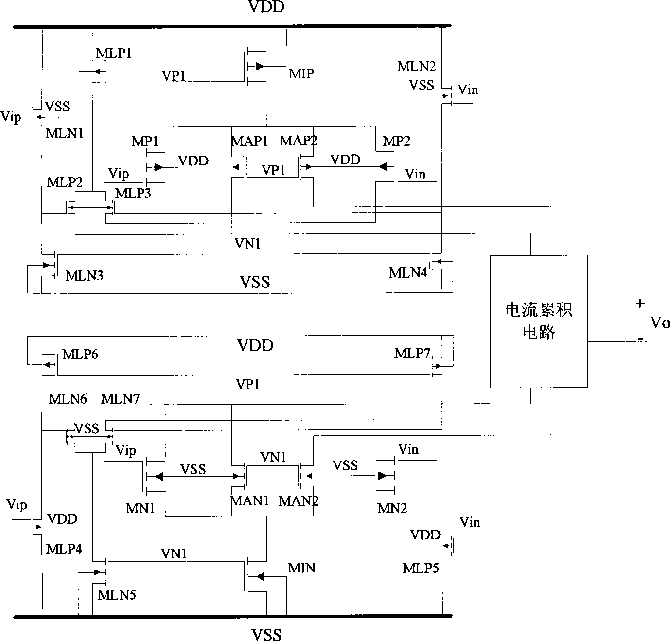
[0014] Such as figure 1 As shown, this embodiment includes NMOS transistors MN1, MN2, MIN, MAN1, MAN2, MLN1-MLN7 with normal thresholds, PMOS transistors MP1, MP2, MIP, MAP1, MAP2, MLP1-MLP7 with normal thresholds, except for MLP2 and MLP3, The substrate terminals of other NMOS transistors and PMOS transistors are respectively connected to the low power supply VSS and the high power supply VDD.

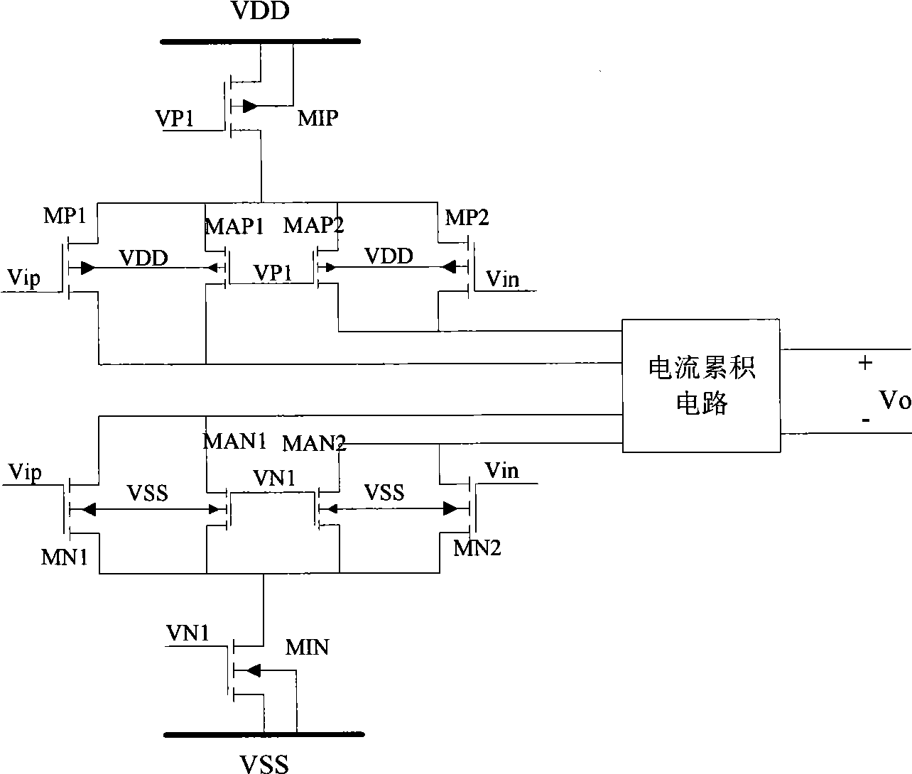
[0015] Among them, NMOS transistors MN1, MN2, MIN, MAN1, MAN2, PMOS transistors MP1, MP2, MIP, MAP1, MAP2 and the current accumulation circuit constitute a fully differential rail-to-rail ...


PUM


Abstract

The invention relates to a low mains voltage fully differential rail-to-rail amplifying circuit in the technical field of integrated circuits, which comprises NMOS transistors with normal threshold, such as MN1, MN2, MIN, MAN1, MAN2 and MLN1 to MLN7, and PMOS transistors with normal threshold, such as MP1, MP2, MIP, MAP1, MAP2 and MLP1 to MLP7. Other than MLP2 and MLP3, a low power supply VSS and a high power supply VDD are connected with the substrate ends of other NMOS transistors and PMOS transistors respectively. The circuit adopts a pair of the PMOS transistors and a pair of the NMOS transistors to carry out differential input and adopts a pair of additional PMOS transistors and a pair of additional NMOS transistors to carry out current compensation, thus allowing the fully differential rail-to-rail amplifying circuit to have constant current. A voltage shift circuit is used for eliminating dead zones within the input common-mode range under low mains voltage so as to realize the rail-to-rail input under the low mains voltage.

Description

technical field [0001] The invention relates to a rail-to-rail amplifying circuit in the technical field of integrated circuits, in particular to a low power supply voltage fully differential rail-to-rail amplifying circuit based on constant current. Background technique [0002] With the further reduction of the feature size of the CMOS process, the power supply voltage of the integrated circuit is also continuously reduced. For the integrated amplifier circuit, the common-mode input range is also reduced. Therefore, the rail-to-rail amplifier circuit whose common mode input range can reach the power supply voltage has become a key part of the analog integrated circuit design. Rail amplifier circuits have become the focus of analog integrated circuit design. [0003] Found through literature search to prior art, J.F.Duque-Carrillo et al published ("Robustand universal constant-gm circuit techniques") on Electronics Letters (Electronics Letters periodical) (2002, 9 phases, ...

Claims


Application Information

Patent Timeline
Patent Type & Authority Applications(China)
IPC IPC(8): H03F3/45G05F3/24
Inventor 隋晓红
Owner SHANGHAI JIAO TONG UNIV
Learn More