Movement compensation method of real time electronic steady image based on motion state recognition

A motion state, motion compensation technology, applied in the field of motion compensation

Inactive Publication Date: 2009-08-19
BEIHANG UNIV
View PDF2 Cites 49 Cited by
  • Summary
  • Abstract
  • Description
  • Claims
  • Application Information

AI Technical Summary

Problems solved by technology

The present invention can effectively solve the image stabilization problem when a variety of complex motion states and shooting modes are freely switched, can realize the image stabilization requirements of video image sequences captured randomly in complex environments, and achieve the purpose of outputting stable videos in real time, which can not only improve Visual observation effect, and can guarantee the accuracy of subsequent information processing

Method used


Image

  • Movement compensation method of real time electronic steady image based on motion state recognition
  • Movement compensation method of real time electronic steady image based on motion state recognition
  • Movement compensation method of real time electronic steady image based on motion state recognition

Examples


Embodiment Construction

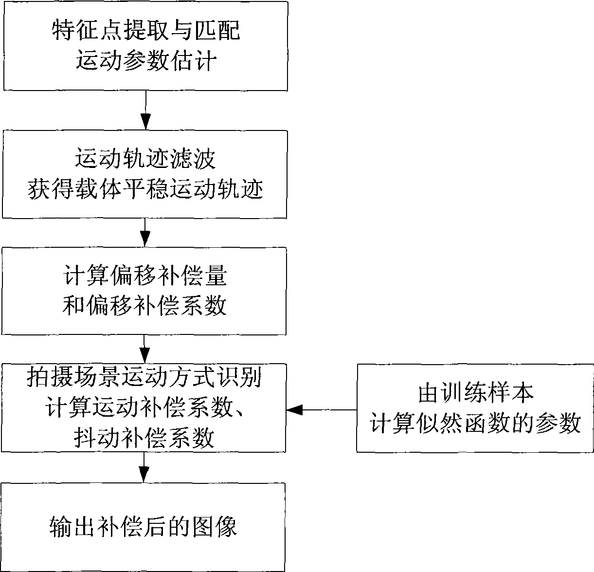
[0079] refer to figure 1 , a motion compensation method based on motion state recognition in real-time electronic image stabilization of the present invention, its specific implementation steps are as follows:

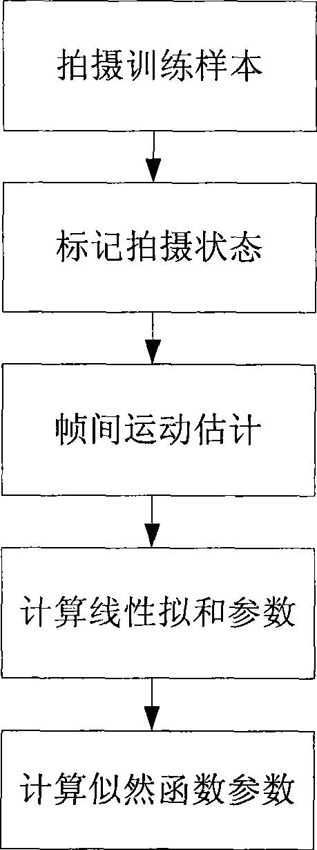
[0080] Step 1. Likelihood Function Training for Motion Types

[0081] In order to identify the motion state and type of the shooting scene, the likelihood function of the motion type needs to be trained before image stabilization; in the following step 5, the maximum posterior probability method is used to estimate the motion state, and the likelihood function of each state However, the function must be trained through samples, and the specific implementation process is as follows:

[0082] (1), collect training video samples

[0083] According to its application background, such as vehicle-mounted, airborne, and handheld devices, collect the required training samples, that is, collect video samples of scanning and staring shooting types for the application backgroun...


PUM


Abstract

The invention relates to a motion compensation method based on motion state identification in real-time electronic image stabilization, which comprises the steps that: (1) the likelihood function of a motion type is trained; (2) a motion compensation model is built; (3) the offset of a current frame image with correspondence to the center point of a window is calculated; (4) a component motion is filtered, and an ideal motion parameter and a linear fitting parameter are calculated; (5) the motion state of the current frame image is identified, and a motion compensation parameter is set up; (6) according to the motion compensation quantity of three stages, the output position of the current frame image is determined. The method divides motion compensation into the three parts of jitter compensation, smooth motion compensation and deviation compensation; camera motion is divided into staring shoot and scanning shoot; by identifying the current motion state of a scene, the proportion of the three motion compensation parameters are adaptively adjusted, therefore the 'too smooth' and the 'lack of smooth' problems during the motion compensation solving process is solved. The motion compensation method has the advantages that, the image stabilization problems in various complicated motion states and during free shooting mode conversion are effectively solved, and the objective to real-timely output stable video is achieved.

Description

(1) Technical field [0001] The invention belongs to the application field of image processing technology, and relates to a motion compensation method in real-time electronic image stabilization of video images. This method can eliminate the influence of the irregular motion of the shooting carrier in the video image sequence through inter-frame motion estimation and motion compensation, and output stable video images in real time, so as to improve the image quality of video equipment and the accuracy of subsequent processing of the system sex. (2) Technical background [0002] With the wide application of optical imaging equipment in transportation, medical treatment, precision guidance, military reconnaissance and aerospace fields, the requirements for imaging quality are getting higher and higher. The video image signals collected by photography platforms such as handheld camera equipment, vehicle camera systems, aircraft, missiles, and satellites include not only the smo...

Claims


Application Information

Patent Timeline
Patent Type & Authority Applications(China)
IPC IPC(8): H04N7/26G06T7/20H04N19/51
Inventor 赵丹培冯昊姜志国安萌
Owner BEIHANG UNIV
Why Eureka
Try Eureka