Open cycle internal combustion engine

An open-cycle, internal-combustion engine technology, applied in the direction of internal combustion piston engines, combustion engines, mechanical equipment, etc., which can solve the problems of restricted use, high cost, acquisition cost, and low supply of reconstruction

Inactive Publication Date: 2009-08-19
T·M·范布拉瑞科姆
View PDF0 Cites 8 Cited by
  • Summary
  • Abstract
  • Description
  • Claims
  • Application Information

AI Technical Summary

Problems solved by technology

[0011] As mentioned earlier, turboshaft engines are only available at very high cost, which limits their use in military and commercial aircraft, military transport such as tanks and ships, and large power plants where , acquisition fees and supply for reconstruction are not much in contention
In addition to the high cost of foreign materials required in turboshaft engines, additional costs are incurred due to the high rotational speed of turboshaft engines, which require special bearings and lubrication systems, where there is no tolerance for tolerance in manufacturing

Method used


Image

  • Open cycle internal combustion engine
  • Open cycle internal combustion engine
  • Open cycle internal combustion engine

Examples


Embodiment Construction

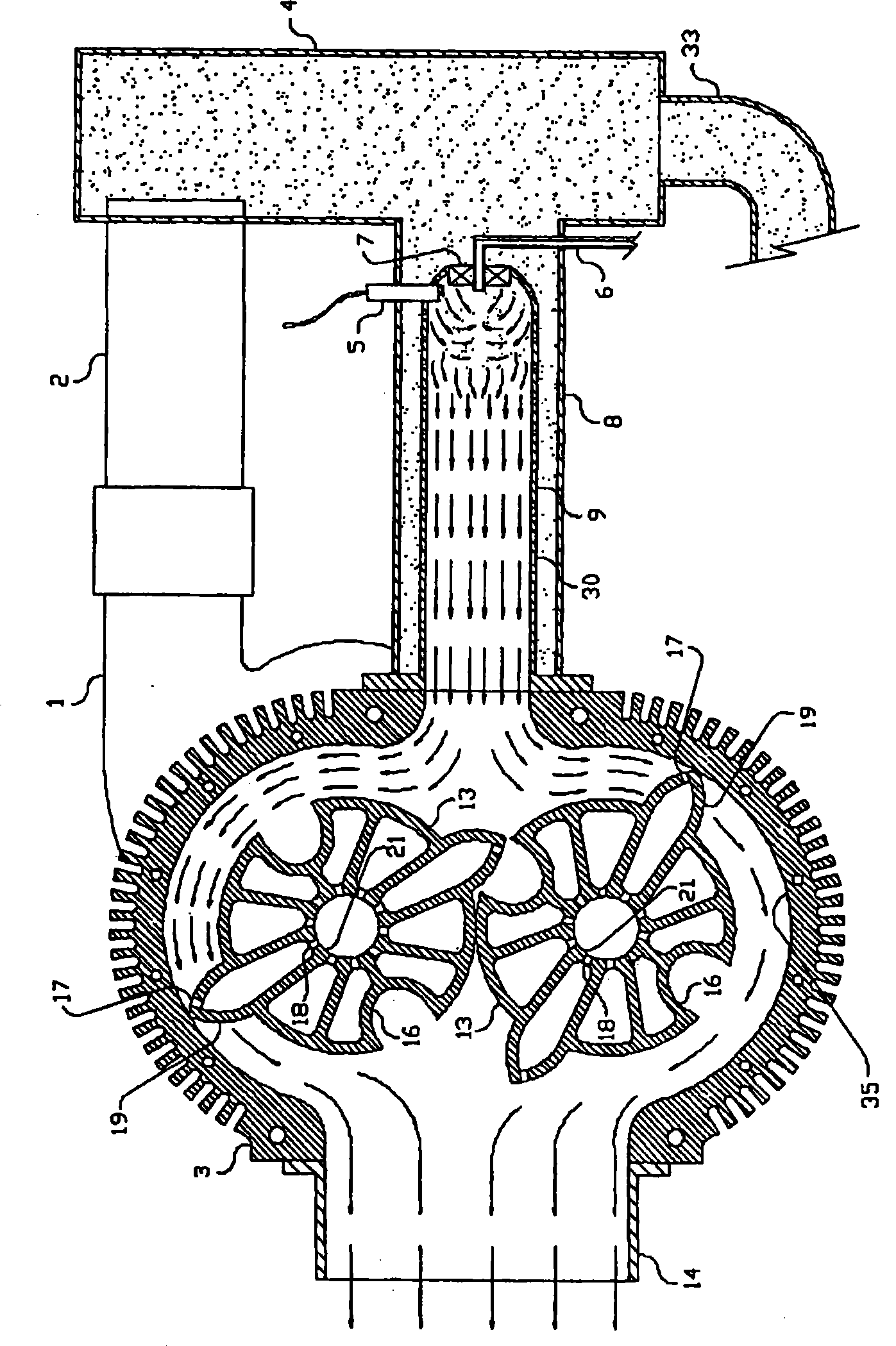
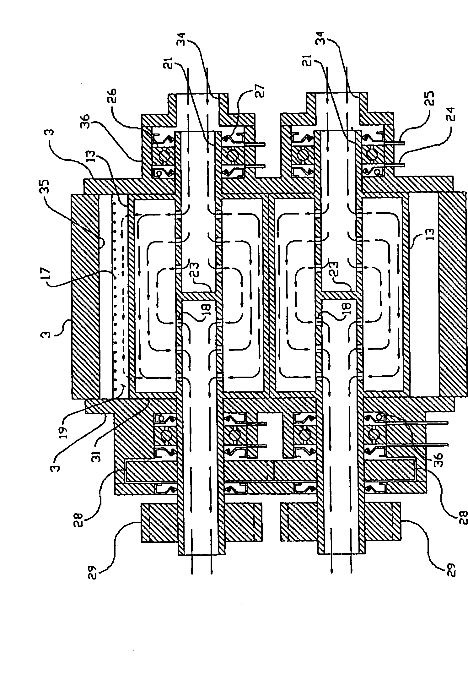
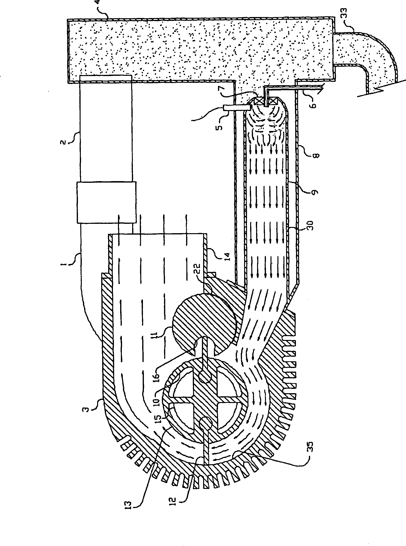
[0025] figure 1 and 1A A cross-sectional view of a preferred embodiment of the open cycle internal combustion engine of the present invention is shown. figure 1 The section of is obtained by cutting the line through the midpoint of the rotor 13, the combustor lining 9 and the high pressure 4. exist Figure 1A The rotor shaft piston 23 shown in is not depicted in this view. Figure 1A The section is taken longitudinally through the center of the hollow rotor shaft.

[0026] working:

[0027] The centrifugal compressor 1 driven by a drive gear 29 on one of the rotor shafts 21 forces compressed air through the compressed air duct 2 and into the high pressure chamber 4 . High pressure chamber 4 delivers compressed air to combustor shroud 8 , which in turn conducts compressed air to swirler nozzle 7 and combustor liner 9 . Fuel is introduced into the combustion zone by supplying fuel metering nozzles 6 fed by fuel metering pumps of conventional design, not shown in the figure...


PUM


Abstract

An open-cycle engine in which rotary power is produced by the pressure of hot gasses against confined, rotating vanes.

Description

[0001] This application is based on US Provisional Application No. 60 / 841,918, filed September 5, 2006. technical field [0002] The present invention is an improved Brayton or open cycle type internal combustion engine. An open cycle engine may be defined as an internal combustion engine in which the compression of the air and the combustion of the fuel occur continuously as the fuel is mixed with the compressed air. [0003] A jet turbine engine producing shaft power is most representative of open cycle engines of the prior art. These types of engines are known as turboshaft engines and are typically used to power helicopters and larger fixed-wing aircraft because of their efficiency, light weight, clean burning, multi-fuel capabilities, and smooth rotation without Reciprocates the part. Background technique [0004] Despite the above features, generally turboshaft engines are not commonly used for powering in public transportation, eg ships, trams, trucks. This is main...

Claims


Application Information

Patent Timeline
Patent Type & Authority Applications(China)
IPC IPC(8): F02K3/00
CPCY02T10/17
Inventor T·M·范布拉瑞科姆
Owner T·M·范布拉瑞科姆
Why Eureka
Try Eureka