Micro-grid system construction method

A micro-grid and power supply technology, applied in the direction of electrical components, circuit devices, battery circuit devices, etc., can solve problems such as increased burden on power companies, and achieve the effect of preventing insufficient capacity or redundant equipment and achieving consistent balance

Inactive Publication Date: 2009-08-19
THE SHIMIZU CONSTRUCTION CO LTD +1
View PDF3 Cites 6 Cited by
  • Summary
  • Abstract
  • Description
  • Claims
  • Application Information

AI Technical Summary

Problems solved by technology

[0003] However, in the power dispatching system using the above-mentioned distributed power supply, if the distributed power supply and the commercial system (power grid of the power company) are used at the same time to make the distributed power supply perform base load (base load) operation, it will become a problem for the power company. Independently assume the ancillary function of voltage or frequency fluctuations, and only seek compensation for load fluctuations in commercial systems, which increases the burden on power companies

Method used


Image

  • Micro-grid system construction method
  • Micro-grid system construction method
  • Micro-grid system construction method

Examples


Embodiment Construction

[0043]Hereinafter, an embodiment of the construction method of the microgrid system according to the present invention will be described based on the drawings. In this embodiment, a case where a certain facility is a specific area and the microgrid system 1 is constructed in the facility will be described as an example.

[0044] First, the microgrid system 1 of the present embodiment will be described.

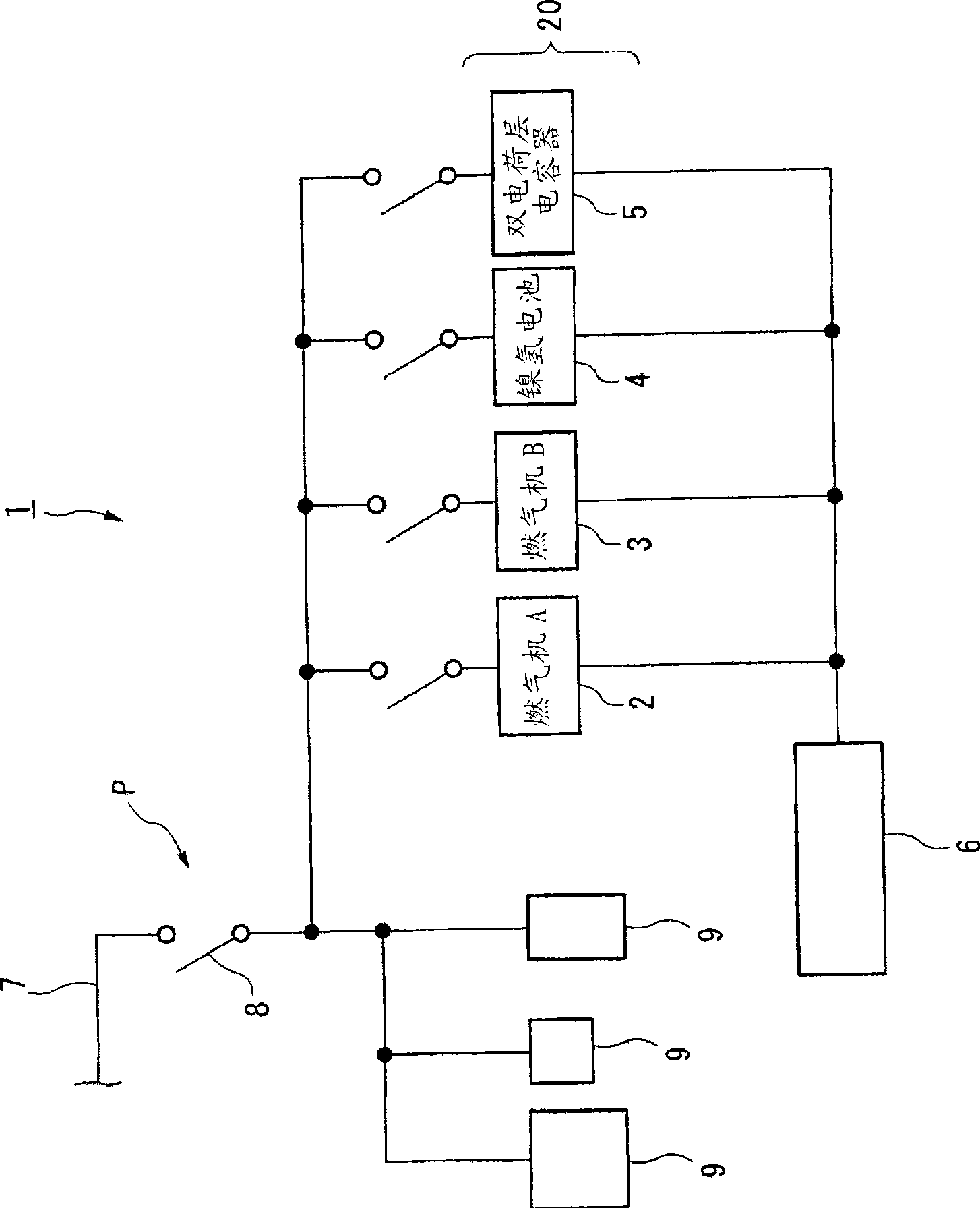
[0045] figure 1 It is a schematic diagram showing the schematic configuration of the microgrid system 1 according to the present embodiment.

[0046] Such as figure 1 As shown, the microgrid system 1 of the present embodiment is to construct a distributed power source 20 including various power sources (gas engine A (2), gas engine B (3), nickel metal hydride battery 4, electric double layer capacitor 5) A system for supplying electric power to loads 9 ... (electrical equipment, etc.) in a specific area by collectively controlling the operating network with the control unit...


PUM


Abstract

A method for building a microgrid system wherein a network is built which integratively controls and operates distributed power supplies including a plurality of types of power supplies so as to supply a power to a particular area. The method comprises a step of determining load variations of the particular area to frequency analyze the data of the load variations; and a step of deciding, based on the frequency response characteristics of the plurality of types of power supplies, share frequencies of which the respective ones of the plurality of types of power supplies take charge, allocating, based on the share frequencies, a frequency analysis result of the load variations to the respective one of the plurality of types of power supplies, and determining a capacity required of the respective one of the plurality of types of power supplies.

Description

technical field [0001] The present invention relates to a construction method of a microgrid system composed of a networked structure of various distributed power sources. Background technique [0002] As is well known, in recent years, the development of various distributed power sources such as natural gas thermal power generation (cogeneration) and fuel cells has been promoted. By adopting such a distributed power supply as self-generating equipment in buildings, excellent overall energy efficiency from thermoelectric supply can be obtained, reduction in emission of global warming gases can be expected, and commercial systems (power purchases from power companies) can be realized There are various advantages such as cost reduction due to the reduction of the contracted power amount and simplification of power distribution equipment, and easy assurance of autonomous stability during earthquakes and fires. Therefore, power dispatching systems using distributed power source...

Claims


Application Information

Patent Timeline
Patent Type & Authority Applications(China)
IPC IPC(8): H02J3/46H02J3/38
CPCH02J3/38H02J7/34
Inventor 下田英介沼田茂生马场旬平仁田旦三
Owner THE SHIMIZU CONSTRUCTION CO LTD
Why Eureka
Try Eureka