Network and method for clock synchronization of clusters in a time triggered network

A time-triggered, time-triggered protocol technology, applied in the direction of synchronization devices, ring networks, wireless network protocols, etc., can solve problems such as slow working speed

Inactive Publication Date: 2009-08-19
NXP BV
View PDF1 Cites 17 Cited by
  • Summary
  • Abstract
  • Description
  • Claims
  • Application Information

AI Technical Summary

Problems solved by technology

these coupling units are essentially capable of distributing information used to align the communi

Method used


Image

  • Network and method for clock synchronization of clusters in a time triggered network
  • Network and method for clock synchronization of clusters in a time triggered network
  • Network and method for clock synchronization of clusters in a time triggered network

Examples


Embodiment Construction

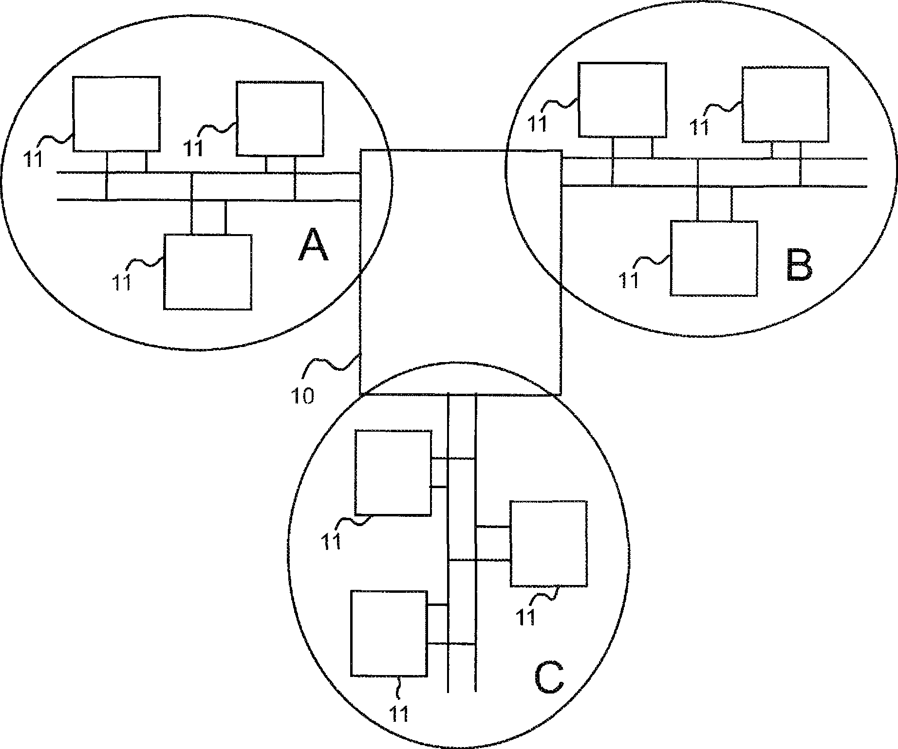
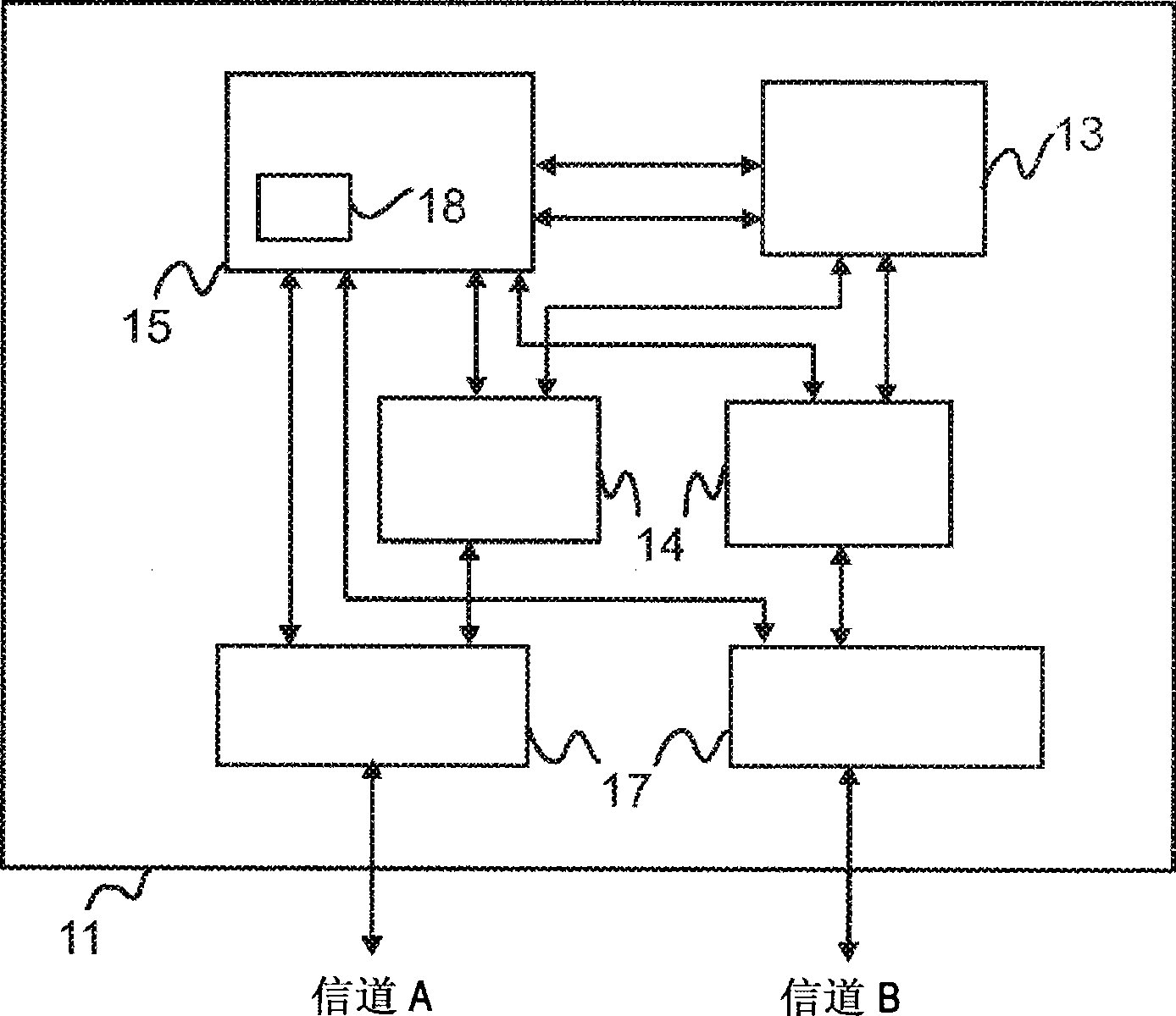
[0028] Such as figure 1 As shown in , a typical fault-tolerant time-triggered network consists of two or more communication channels (channel A and channel B) connected to communication nodes 11. figure 2 Illustrated is a node 11 used in a time-triggered network. Each of these nodes 11 consists of a bus driver 17 , a communication controller 15 , a bus protector 14 for the respective bus driver 17 and an application host 13 . The bus driver 17 transfers the bits and bytes provided by the communications controller 15 onto its associated channel, and in turn provides the communications controller 15 with the information it receives on that channel. Communication controller 15 is connected to both channels and passes relevant data to and receives data from application host 13 , which in turn assembles the received data into frames and passes to bus driver 17 . The communication controller 15 mainly includes a protocol engine and a controller host interface (not shown in the fi...


PUM


Abstract

The invention relates to a network operating on a time triggered protocol using time slots, wherein at least two clusters are included in the network, each cluster includes at least a node. Further, it relates to a method for clock synchronization within a time triggered network. To provide a network and a method reducing the amount of time needed for aligning multiple communication clusters as much as possible it is proposed to provide a network operating on a time triggered protocol using time slots, wherein at least two clusters (A, B, X) are included in the network, each cluster (A, B, X) includes at least a node (11), wherein the node (11) includes a communication controller (15) having a node clock source (18) for determining a timing for the node (11), wherein the clusters (A, B, X) are connected to a coupling unit (10) having a clock alignment control logic (20) comprising a coupling unit clock source (21) which is more accurate than the node clock source (18), wherein the coupling unit clock source (21) is used for aligning the timing between the at least two clusters (A, B, X). Further it is proposed to provide a method for clock synchronization within a time triggered network using time slots, having at least two clusters (A, B, X), wherein each cluster includes at least one node (11), each node (11) comprises a node clock source (18) and a communication controller (15) and the clusters (A, B, X) are connected to a coupling unit (10) having a clock alignment control logic (20) comprising a coupling unit clock source (21) which is more accurate than the node clock source (18), the method comprising the steps of: monitoring the timing of the connected clusters (A, B, X) within the coupling unit (10); increasing or decreasing a cycle length of the timing within the clusters by use of the coupling unit clock source (21).

Description

technical field [0001] The invention relates to a network operating on the basis of a time-triggered protocol using time slots, wherein the network comprises at least two clusters, each cluster comprising at least one node. Furthermore, it concerns a method for synchronizing clocks within a time-triggered network. Background technique [0002] Modern communication systems usually do not consist of a single communication domain. Instead, multiple such communication domains may each be connected using a different communication protocol. [0003] Current in-vehicle networks typically consist of multiple CAN and LIN clusters interconnected by gateway nodes. These protocols are not intended for real-time exchange of security-related information. As the need to implement safety-related functions in vehicles increases, the need to connect safety-related nodes to the network has further increased. Therefore, security-related protocols need to be added to these networks. In part...

Claims


Application Information

Patent Timeline
IPC IPC(8): H04J3/06
CPCH04J3/0694H04J3/0652H04L2012/40215H04L12/43H04L12/44H04J3/0676H04W56/00H04W80/00
Inventor 约恩·翁格曼
Owner NXP BV
Why Eureka
Try Eureka