
High-altitude portable pipeline cutting machine

A pipeline cutting machine and portable technology, applied in the directions of metal processing machinery parts, clamping, support, etc., can solve the problems of irregular project quality of pipeline opening, influence of pipeline node construction process, complicated installation operation, etc., and achieve simple and standard construction process. , light weight, convenient replacement effect

Inactive Publication Date: 2010-11-03
董沛霖
View PDF4 Cites 0 Cited by
  • Summary
  • Abstract
  • Description
  • Claims
  • Application Information

AI Technical Summary

Problems solved by technology

[0003] The purpose of the present invention is to provide a high-altitude portable pipe cutting machine to solve the existing portable pipe cutting machines that are cumbersome to install and operate, heavy in weight, low in construction accuracy, high in cost, and have a large radius of gyration. limited, not suitable for use in high-altitude operations
[0005] The present invention has the following beneficial effects: 1. The present invention solves the problems of the impact of pipeline nodes on construction technology and the influence of irregular pipeline openings on project quality during construction, especially in high-altitude construction

Method used


Image

  • High-altitude portable pipeline cutting machine
  • High-altitude portable pipeline cutting machine
  • High-altitude portable pipeline cutting machine

Examples


specific Embodiment approach 1

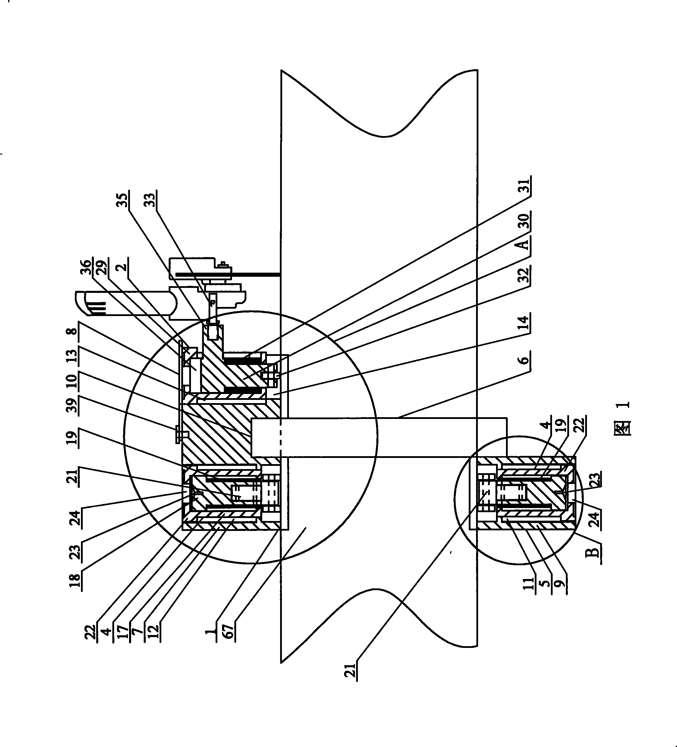
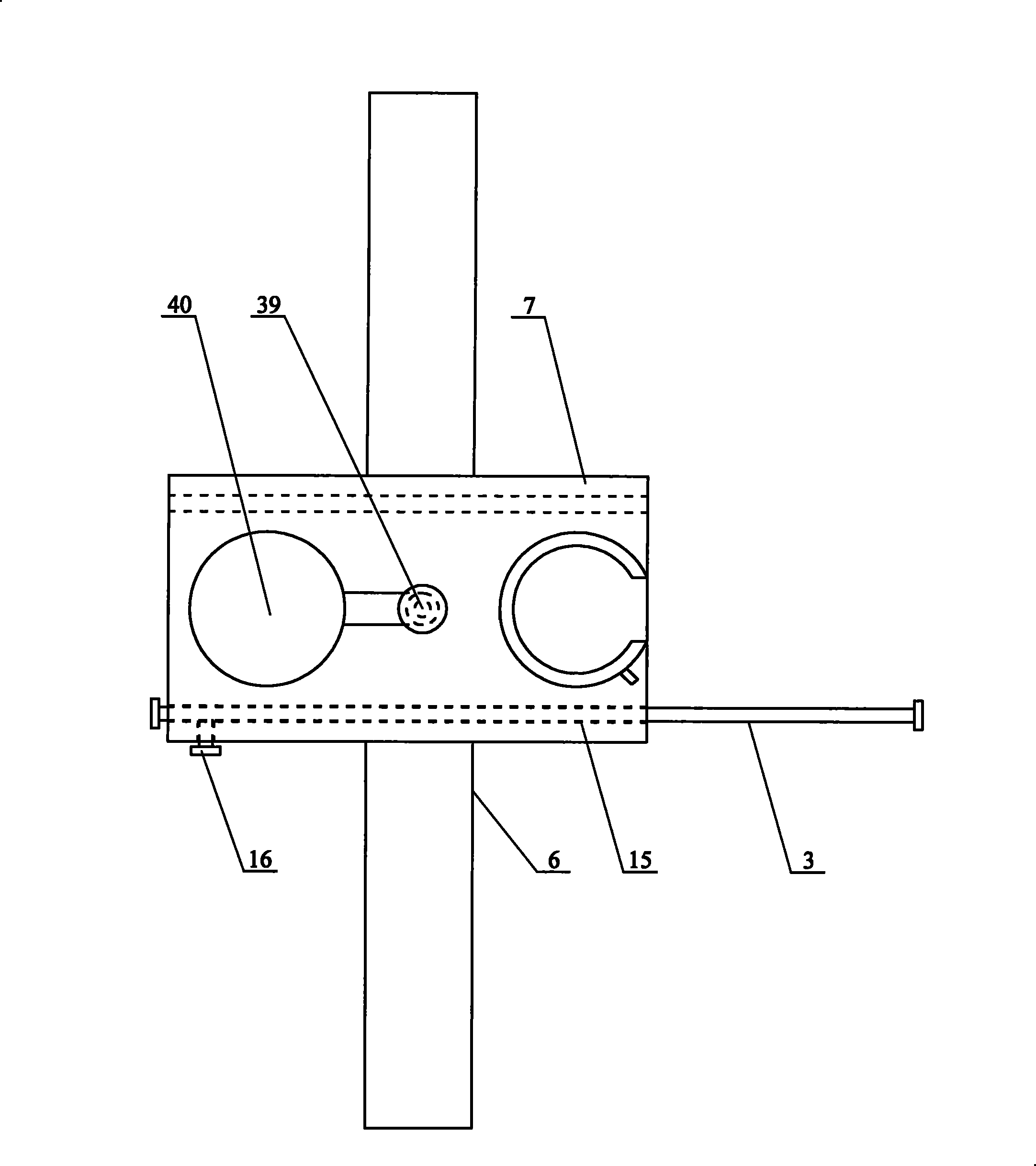
[0009] Specific implementation mode one: combine Figure 1 to Figure 11 To illustrate this embodiment, the pipe cutting machine of this embodiment is composed of a knife rest assembly 1, a knife body frame assembly 2, a positioning scale 3 and two walking mechanisms 4; the knife rest assembly 1 is composed of a knife rest body 5 and The hinged ring frame 6 is composed of; the tool holder body 5 is composed of a tool holder 7, a rotating cover 8 and a running mechanism seat 9; one end of the hinged ring frame 6 is fixed on the arc-shaped In the groove 10, and the hinged end and the open end of the articulated ring frame 6 are exposed outside, the outer side wall of the traveling mechanism seat 9 is affixed to one side of the ring end face of the articulated ring frame 6, and the inside of the traveling mechanism seat 9 Be provided with traveling mechanism chamber 11, be provided with traveling mechanism chamber 12 on the knife rest 7 corresponding with described traveling mecha...

specific Embodiment approach 2

[0010] Specific implementation mode two: combination figure 1 , Figure 7 , Figure 8 and Figure 10 Illustrate the present embodiment, each running gear 4 of the present embodiment is made up of positioning seat 17, positioning rod 18, positioning spring 19, positioning pin 20 and walking carriage 21; Threaded, the locating seat 17 that is contained in the traveling mechanism chamber 11 is threadedly connected with the inwall of the traveling mechanism chamber 11, and the locating seat 17 that is contained in the traveling mechanism chamber 12 is threadedly connected with the inwall of the traveling mechanism chamber 12, and the positioning Rod 18 is contained in the inner cavity of locating seat 17 and is slidably matched with it, and the outer wall of locating rod 18 is provided with shoulder end face, and one end of trolley 21 is contained in the locating bar 18, and trolley 21 is connected with locating bar by locating pin 20. 18 is fixedly connected, the positioning ...

specific Embodiment approach 3

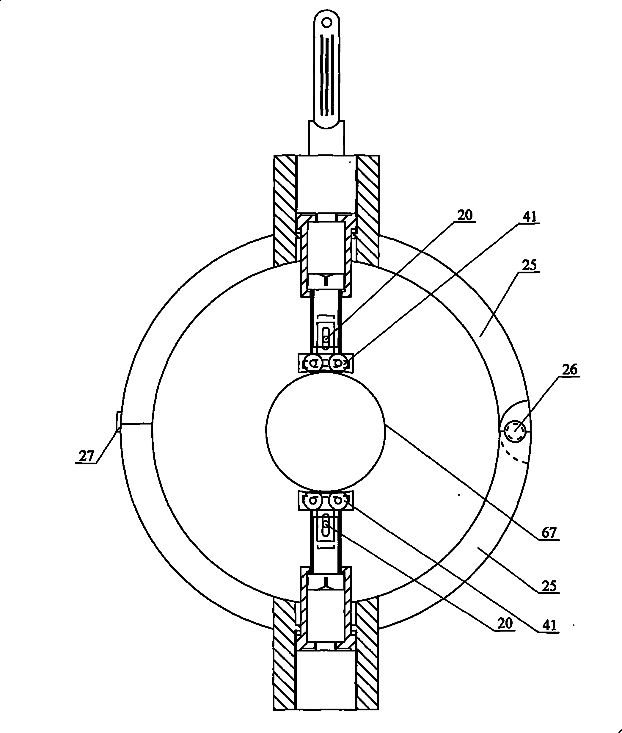
[0011] Specific implementation mode three: combination figure 1 , figure 2 , Figure 4 and Figure 5 Describe this embodiment, the articulated ring frame 6 of this embodiment is made up of rotating shaft 26, lock pin 27 and two semi-circular bodies 25; One end of each semi-circular body 25 is a stepped end 28, each The other end of the semicircular body 25 is a plane end, and the stepped ends 28 of the two semicircular bodies 25 cooperate with each other and are hinged together by the rotating shaft 26 to form the hinged end of the articulated ring frame 6, and the two semicircular The plane end of the ring body 25 constitutes the open end of the hinged ring frame 6 , and locking pins 27 are provided at the plane ends of the two semi-circular bodies 25 . So set, it is easy to open and close. Other compositions and connections are the same as those in Embodiment 1 or 2.


PUM


Abstract

A high-altitude portable pipeline cutting machine relates to a pipeline cutting machine, which aims at the problems of the portable pipeline cutting machines, such as fussy mounting operation, heavy weight, low precision, high cost, large radius of gyration, and unsuitable use in working aloft. A hinged annular shelf is fixedly connected with a knife rest; a running mechanism seat is fixedly connected with the hinged annular shelf; a running mechanism cavity is arranged in the running mechanism seat; a chamber of the running mechanism cavity is arranged on the knife rest; two running mechanisms are respectively arranged in the running mechanism cavity and the chamber of the running mechanism cavity; a large-diameter crown arc groove and a small-diameter crown arc groove which are mutuallycommunicated are arranged on the knife rest and are used as running cavities of a knife body frame; a knife body frame assembly is arranged in the running cavity of the knife body frame; the upper end of the knife body frame assembly is limited by a rotating cover arranged on the upper end surface of the knife rest; a locating staff gauge is fixedly arranged in a staff gauge mounting hole on the knife rest. The invention has light weight and small radius of gyration, good compatibility and low cost; moreover, the specification span of the pipeline which can be cut by the machine is large. Besides, the high-altitude portable pipeline cutting machine is suitable to be used for working aloft.

Description

Technical field [0001] The invention involves a pipeline cutting machine. Background technique [0002] In the pipeline construction, pipelines need to lead the branch pipelines or add valve and other pipes in turning, branches, and working points.If you do n’t go up at high altitude, you ca n’t go up, so you can only measure the size in the air, and then return to the ground to get the feeding. The work is cumbersome.At present, the pipeline cutting machines on the market are mostly used on the ground. The equipment is complex and large. Although the accuracy is high, the installation operation is inconvenient and it is not suitable for high -altitude operations.There are also portable pipeline cutting machines. One is to use flame cutting methods. The installation is more complicated, the construction accuracy is low, and the weight is large (generally about 15-20 kg); the other is to use cold cutting methods., High cost, poor stability, affecting construction accuracy, large r...

Claims


Application Information

Patent Timeline
Patent Type & Authority Patents(China)
IPC IPC(8): B26D1/12B26D7/26B26D7/00B23Q3/02
Inventor 董沛霖
Owner 董沛霖
Learn More