Tilt rotor vector propeller based on wave energy

A technology of vector thrusters and tilting rotors, which is applied to ocean energy power generation, machines/engines, underwater operation equipment, etc., can solve the problems of accelerated water flow, low efficiency, and low action sensitivity, and achieve the effect of improving steering ability

Inactive Publication Date: 2012-07-25
NAT UNIV OF DEFENSE TECH
View PDF0 Cites 1 Cited by
  • Summary
  • Abstract
  • Description
  • Claims
  • Application Information

AI Technical Summary

Problems solved by technology

Ordinary propeller propellers have a simple structure and are the most widely used, and have high propulsion efficiency, but it is difficult for a single ordinary propeller propeller to control the direction and attitude of the propelled object underwater; Invented by Cotter in 1934, it is a specially designed sleeve or duct on the outside of the propeller. When the propeller rotates forward, a negative pressure zone is formed in the front and a positive pressure zone is formed in the rear, thereby generating forward pressure. The thrust includes the thrust brought by the propeller's own rotation and the thrust generated on the duct, and also accelerates the water flow at the paddle disc, which improves the propulsion efficiency. Compared with the common propeller propeller with the same efficiency, the ducted propeller propels The size of the propeller is much smaller, which is conducive to the overall design of the robot and is easy to operate; the main working parts of the flat-rotating propeller are composed of 4-6 blades protruding from a disc, and the axis of the blade is in line with the disc. Vertically, the disk is connected to the propulsion shaft through the gear, by changing the relative position of the paddle and the disk, the thrust in any direction can be generated in a plane at right angles to the shaft, without rudder and rotating shaft, it has excellent Maneuverability and maneuverability, but because several blades cannot be in an effective propulsion state at the same time, the efficiency is much lower than that of ordinary propellers
However, the existing underwater thrusters are limited by propulsion technology, and there are still problems such as difficult attitude adjustment, low action sensitivity, and inability to adapt to complex changes in underwater topography.

Method used


Image

  • Tilt rotor vector propeller based on wave energy
  • Tilt rotor vector propeller based on wave energy
  • Tilt rotor vector propeller based on wave energy

Examples


Embodiment Construction

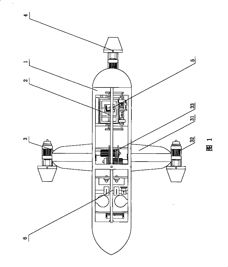
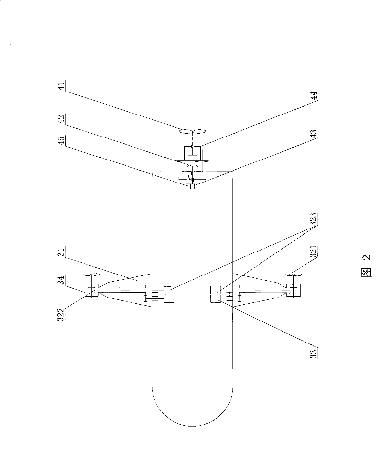
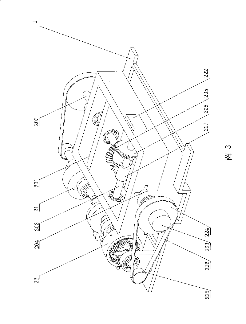
[0056] Such as figure 1 As shown, the tilt rotor vector propulsion device based on wave energy of the present invention includes a fuselage frame 1, a wave energy conversion device 2, a tilt rotor vector propulsion device 3, an empennage vector propulsion device 4, a storage battery 5 and a gliding propulsion control device 6. The tilt rotor vector propulsion device 3 and the empennage vector propulsion device 4 are the main power devices of the propeller, and both can adjust the propulsion direction. In the present embodiment, the tilt rotor vector propulsion device 3 is provided with two groups, and is respectively installed on the fuselage On both sides of the frame 1 ; one set of empennage vector propulsion device 4 is installed at the tail end of the fuselage frame 1 . The gliding propulsion control device 6 is installed on the front portion of the fuselage frame 1, and is mainly used to adjust the buoyancy of the propeller in water. The wave energy conversion device 2 ...


PUM


Abstract

The invention discloses a tilt rotor vector propeller based on wave energy. The propeller comprises an airframe which is equipped with a wave energy conversion device, an accumulator, and at least two sets of tilt rotor vector propulsion devices. The wave energy conversion device and the tilt rotor vector propulsion devices are connected with the accumulator respectively, and the tilt rotor vector propulsion device comprises a hang-glider, a propulsion mechanism, a tilt drive motor and a tilt frame. One end of the hang-glider is fixed on the airframe, and the tilt frame is supported on the other end of the hang-glider. An output terminal of the tilt drive motor is connected with the tilt frame, and the propulsion mechanism is arranged on the tilt frame. The tilt rotor vector propeller based on the wave energy has the advantages of converting the wave energy into electric energy, supporting long-distance navigation, and realizing complicated actions such as rapid turning and horizontaltumbling and the like.

Description

technical field [0001] The present invention relates to an underwater thruster, in particular to a tilting rotor vector thruster based on wave energy. Background technique [0002] The underwater thruster is actually a remotely operated vehicle. There are many types of propulsion methods for existing underwater propellers, such as ordinary propeller propellers, ducted propeller propellers, flat-rotating propellers, channel propellers and emerging magnetic fluid propellers, etc., and there are many types. Ordinary propeller propellers have a simple structure and are the most widely used, and have high propulsion efficiency, but it is difficult for a single ordinary propeller propeller to control the direction and attitude of the propelled object underwater; Invented by Cotter in 1934, it is a specially designed sleeve or duct on the outside of the propeller. When the propeller rotates forward, a negative pressure zone is formed in the front and a positive pressure zone is fo...

Claims


Application Information

Patent Timeline
Patent Type & Authority Patents(China)
IPC IPC(8): B63G8/08F03B13/14
CPCY02E10/38Y02E10/30
Inventor 尚建忠罗自荣王晓明丛楠
Owner NAT UNIV OF DEFENSE TECH
Why Eureka
Try Eureka