Quenching unit of aluminum alloy plate and method thereof
A technology of aluminum alloy plate and quenching device, which is applied in the direction of quenching device, quenching agent, heat treatment process control, etc., can solve the problems of plate residual stress, poor performance uniformity and stability, large quenching residual stress of plate, etc., and achieve reduction Residual stress, increasing hardening depth, and reducing the effect of quenching residual stress
- Summary
- Abstract
- Description
- Claims
- Application Information
AI Technical Summary
Problems solved by technology
Method used
Image

Examples
Embodiment 1
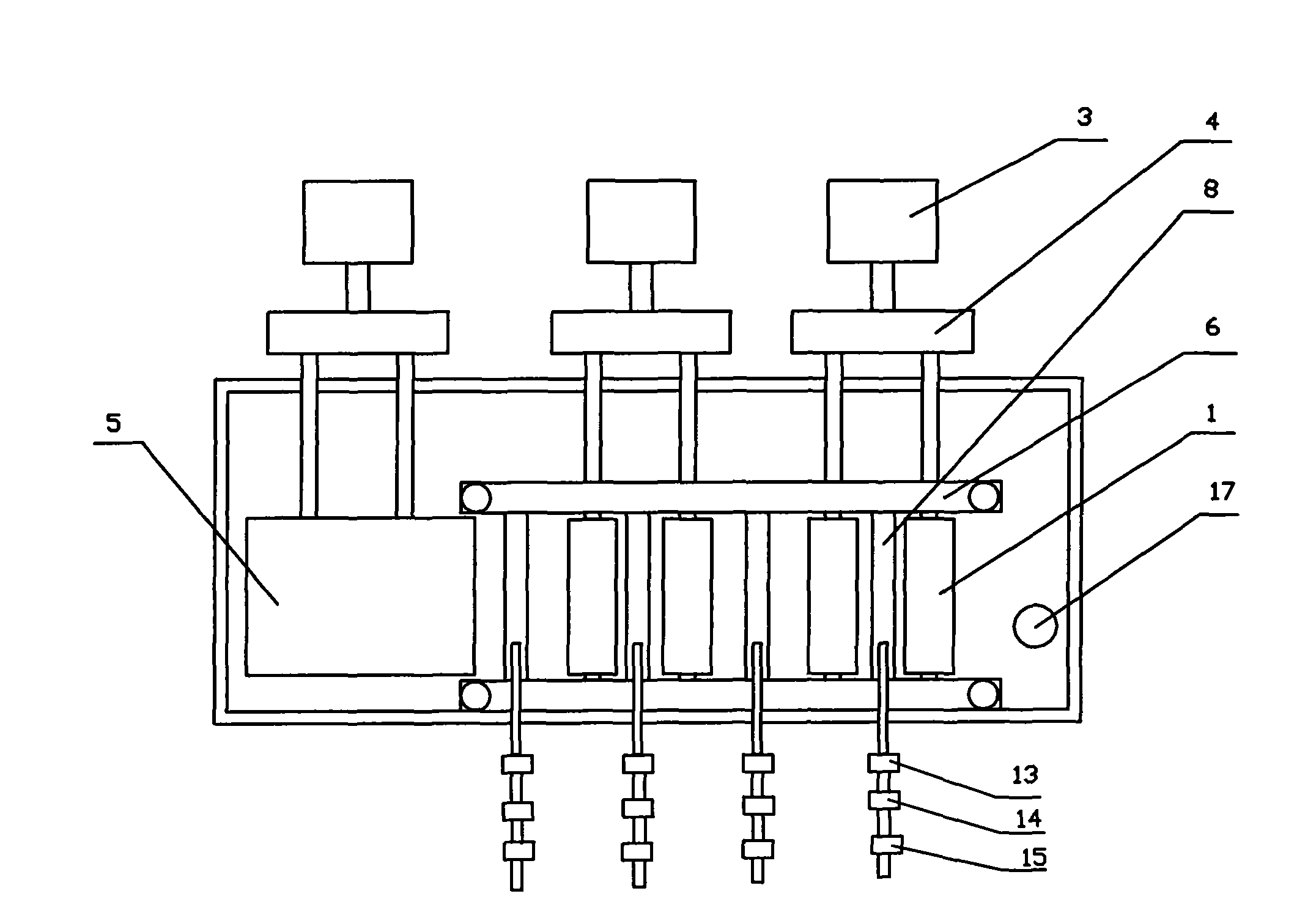
[0050] Embodiment 1: Alloy A, the size of the aluminum alloy plate is 80mm × 500mm × 1500mm, 4 pairs of nozzle rows are arranged, respectively have the characteristics of the four types of nozzle rows described in the present invention, and the angle between the direction of spraying water and the plane of the roller table during quenching Adjust it to 90°, and adjust the vertical distance between the nozzle and the surface of the aluminum alloy plate to 150mm. After the aluminum alloy plate is sent to the roller table, it passes through the first pair and the second pair of nozzle rows at a speed of 100mm / s. Through the third and fourth pairs of nozzle rows, the flow density of water sprayed by the first pair of nozzle rows on the aluminum alloy plate is 10L / (m 2 s), the pressure of water leaving the nozzle is 0.5MPa, and the flow density of the second pair of nozzles spraying water on the aluminum alloy plate is 20L / (m 2 s), the pressure of water leaving the nozzle is 0.3MPa...
Embodiment 2
[0051] Embodiment 2: Alloy B, the size of the aluminum alloy plate is 120mm × 500mm × 4000mm, this embodiment designs 6 pairs of nozzle rows, wherein the first pair of nozzle rows has the characteristics of the first type of nozzle rows described in the present invention, the second The pair and the 3rd pair of nozzle rows have the characteristics of the second type of nozzle rows described in the present invention, the 4th pair of nozzle rows have the characteristics of the third type of nozzle rows described in the present invention, and the 5th pair and the 6th pair of nozzle rows have the characteristics of the present invention. The characteristics of the fourth type of nozzle row described above; during quenching, the angle between the direction of spraying water and the plane of the roller table is adjusted to 45°, the vertical distance between the nozzle and the surface of the aluminum alloy plate is adjusted to 50mm, and the distance between the nozzle and the surface o...
Embodiment 3
[0052] Embodiment 3: C alloy, the size of the aluminum alloy plate is 150mm × 500mm × 4000mm, set 4 pairs of nozzle rows, respectively have the characteristics of the four types of nozzle rows described in the present invention, the direction of spraying water above the roller table and the direction of the roller table during quenching The included angle of the plane is adjusted to 65°, the angle between the direction of spraying water under the roller table and the plane of the roller table is adjusted to 65°, the vertical distance between the nozzle and the surface of the aluminum alloy plate is adjusted to 75mm, and the aluminum alloy plate is sent to the roller table at a rate of 300mm / The speed of s passes through the first pair of nozzle rows and the second pair of nozzle rows in turn, passes through the third pair of nozzle rows at a speed of 200mm / s, passes through the fourth pair of nozzle rows at a speed of 100mm / s, and passes through the first pair of nozzle rows se...
PUM
 Abstract
Description
Claims
Application Information
 - Generate Ideas
- Intellectual Property
- Life Sciences
- Materials
- Tech Scout
- Unparalleled Data Quality
- Higher Quality Content
- 60% Fewer Hallucinations
Browse by: Latest US Patents, China's latest patents, Technical Efficacy Thesaurus, Application Domain, Technology Topic, Popular Technical Reports.
© 2025 PatSnap. All rights reserved.Legal|Privacy policy|Modern Slavery Act Transparency Statement|Sitemap|About US| Contact US: help@patsnap.com