Hermetic type compressor

A compressor, airtight technology, applied in the direction of compressors, refrigerators, mechanical equipment, etc., can solve the problems of enhanced environmental impact, high risk of fire and explosion, waste of refrigerator oil, etc., to achieve less refrigerator oil and less dangerous The effect of small, low amount of refrigerant

Active Publication Date: 2009-08-26
MITSUBISHI ELECTRIC CORP
View PDF2 Cites 3 Cited by
  • Summary
  • Abstract
  • Description
  • Claims
  • Application Information

AI Technical Summary

Problems solved by technology

If a large amount of refrigerant is enclosed, the risk of fire and explosion in this part increases.
[0015] Also, in the case of disposing of hermetic compressors, they are disassembled and collected separately for iron, aluminum, copper, etc., but the

Method used


Image

  • Hermetic type compressor
  • Hermetic type compressor
  • Hermetic type compressor

Examples


Embodiment approach 1

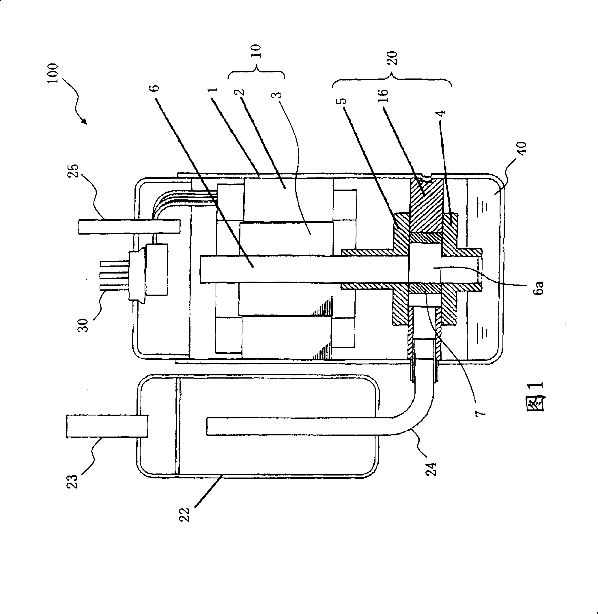
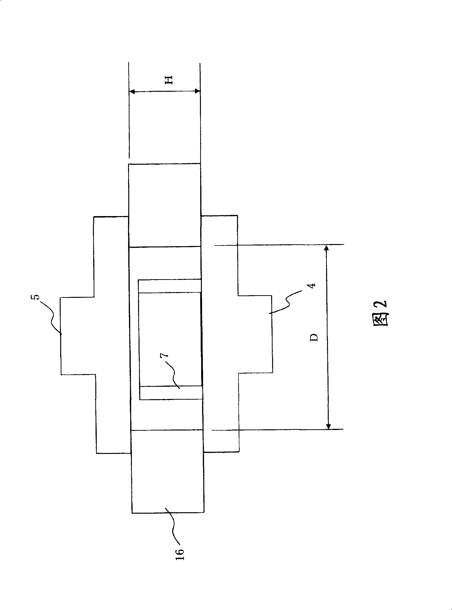
[0023] figure 1 , figure 2 is a drawing showing Embodiment 1, figure 1 is a longitudinal sectional view schematically showing the hermetic compressor 100, figure 2 It is a longitudinal sectional view of main parts of the hermetic compressor 100 .

[0024] refer to figure 1 The structure of the hermetic compressor 100 will be described. The hermetic compressor 100 will be described using a rotary compressor as an example. However, it is also applicable to scroll compressors other than rotary compressors. The hermetic compressor 100 houses a compression mechanism unit 20 and a motor 10 that drives the compression mechanism unit 20 in a hermetic container 1 .

[0025] The motor 10 has a stator 2 and a rotor 3 rotating inside the stator 2 . Electric power is supplied to the stator 2 from the glass terminal 30 . The motor 10 generally uses a brushless DC motor, an induction motor, or the like.

[0026] The compression mechanism part 20 has the cylinder 16, and the outer...

Embodiment approach 2

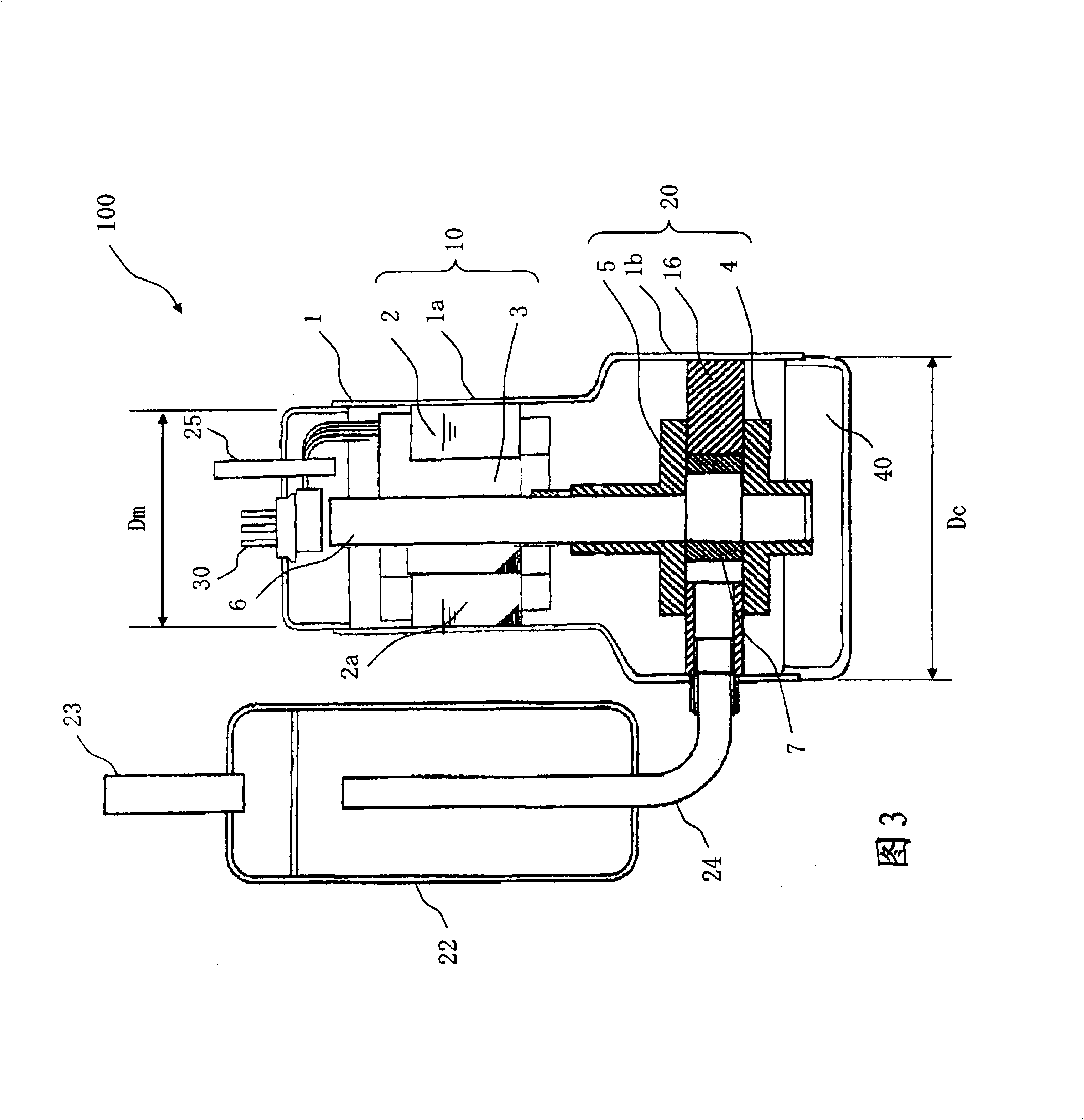
[0042] image 3 It is a drawing showing Embodiment 2, and is a longitudinal sectional view schematically showing a hermetic compressor 100 .

[0043] image 3 The structure of the shown hermetic compressor 100 is the same as that of figure 1 The hermetic compressor 100 is the same.

[0044] (1) The outer diameter Dm of the motor 10 is made smaller than the outer diameter Dc of the compression mechanism part 20 .

[0045] (2) Accordingly, the inner diameter of the portion 1 a covering the motor 10 of the airtight container 1 is smaller than the inner diameter of the portion 1 b covering the compression mechanism portion 20 of the airtight container 1 .

[0046] The motor 10 is fitted and fixed to the inner periphery of the airtight container 1 by caulking or the like.

[0047] Here, the output of the electric motor 10 of the hermetic compressor 100 will be described. In a normal hermetic compressor 100 , the refrigerant changes due to constraints of production equipment, ...

Embodiment approach 3

[0056] In Embodiment 2, the outer diameter Dm of the motor 10 was made smaller than the outer diameter Dc of the compression mechanism part 20, but in this embodiment, the core 2a of the motor 10 is made The width (length in the axial direction) of the motor 10 is smaller than that of the core 2a of the motor 10 set for conventional refrigerants such as R410A, and the volume of the core 2a used in the motor 10 is reduced to adjust the output of the motor 10. Along with this, the height of the airtight container 1 covering the motor 10 is also reduced. Accordingly, the internal volume of the airtight container 1 is reduced.

[0057] It is assumed that the output of the motor 10 is proportional to the volume of the core 2a (the entirety of the stator and the rotor). The outer diameter of the motor 10 is made constant. Since the outer diameter of the motor 10 is constant, the core width H of the motor 10 can also be reduced to 0.9H when the output that the motor 10 must generat...


PUM


Abstract

The invention provides a device using HC refrigerant to cool a loop, namely a safe hermetic type compressor which can reduce danger of fire and explosion when the refrigerant is accidentally leaked. The hermetic type compressor 100 according to the invention comprises, inside a hermetic container 1, a compressing mechanism portion 20 and an electric motor 10 for driving the compressing mechanism portion 20, and performs compression of the refrigerant continuously by dividing a compression room with a vane into a high-pressure room and a low-pressure room. The compression room is composed of a cylinder 16 that disposes therein a rolling piston 7 fitted to an eccentric axis 6a of the crankshaft 6 rotated by the electric motor 10, and a cylinder head 4 and a frame 5 that block both ends of the cylinder 16 in an axial direction. According to the hermetic type compressor 100 using the HC refrigerant, the electric motor is fitted and fixed to an inner peripheral plane of the hermetic container. An outer diameter of the electric motor is less than an outer diameter of the compressing mechanism portion. For the cylinder having an inner diameter D and a height H, D/H is set to more than 0.5 and less than 0.6.

Description

technical field [0001] The present invention relates to a hermetic compressor that can be suitably used in, for example, refrigeration equipment, air conditioning equipment, and hot water supply equipment. Background technique [0002] In a refrigerating cycle device that uses a flammable or toxic refrigerant as the primary refrigerant and other secondary refrigerants, in order to realize the miniaturization of the equipment, it is proposed to drive and use it by the same driving mechanism as the compressor. A side-pump refrigerating cycle device, the refrigerating cycle device has: a main refrigerant circuit that connects the compressor and the decompressor through piping, and encloses the main refrigerant inside; and connects the use-side heat exchanger and the use-side pump with piping , and seal the use-side refrigerant into the internal use-side refrigerant circuit; connect the heat source side heat exchanger and the heat source side pump with piping, and seal the heat ...

Claims


Application Information

Patent Timeline
IPC IPC(8): F04B39/12
CPCF04C18/3564F04C23/008F25B2400/12F04C2270/70F25B31/026F25B2500/01F04C2240/30F05B2210/12F05B2210/14Y10S417/902
Inventor 佐藤幸一前山英明
Owner MITSUBISHI ELECTRIC CORP
Why Eureka
Try Eureka