Metal plastic composite tube with thermoplastic tube end contact flange
A technology for connecting flanges and metal plastics, applied in the direction of pipeline connection layout, pipe/pipe joints/pipe fittings, pipes, etc., can solve the problems of disappearance of anti-corrosion function, inconvenient use, accelerated corrosion of fluid medium, etc., to increase reliability, increase Application properties, the effect of increasing corrosion resistance and thermal insulation properties
- Summary
- Abstract
- Description
- Claims
- Application Information
AI Technical Summary
Problems solved by technology
Method used
Image

Examples
Embodiment 1
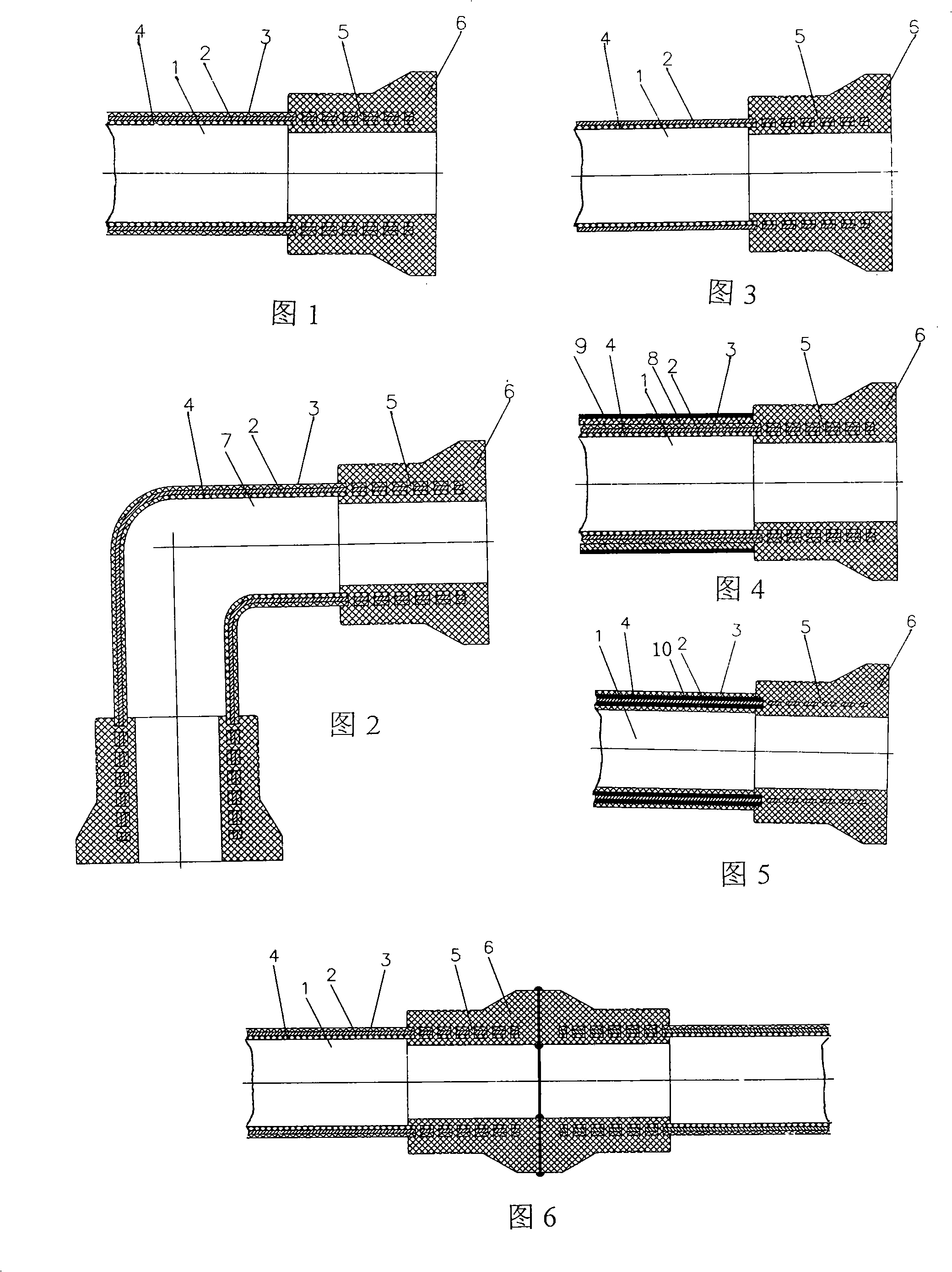
[0026] figure 1 Figure 1 of this example is given. In the metal-plastic composite pipe 1 in the present embodiment 1, there is a cylindrical metal pipe wall 2 with or without holes (can be a seamless steel pipe or other seamless metal pipe, or vertically butt or overlap with an aluminum strip or a steel strip and pass through The cylindrical metal skeleton formed by welding), the cylindrical metal pipe wall 2 has a layer of high-density polyethylene plastic outer layer 3 and plastic inner layer 4 on the inside and outside, respectively, and the composite pipe wall at the end of the metal-plastic composite pipe in the plastic inner layer There are many holes 5, and these holes 5 are filled with thermoplastics that have thermal fusion connection ability with the plastic outer layer 3 and the plastic inner layer 4, and the thermoplastics wrap the cylindrical metal pipe wall through the holes and connect with the plastic outer layer 3 and the plastic inner layer. The layers 4 are...
Embodiment 2
[0028] figure 2 Figure 2 of Embodiment 2 of the present invention is given. Embodiment 2 is basically the same as Embodiment 1. The difference is that the metal-plastic composite pipe is a 90° composite pipe joint 7 .
Embodiment 3
[0030] image 3 Figure 3 of Embodiment 3 of the present invention is given. Embodiment 3 is basically the same as Embodiment 1. The difference is that there is no plastic outer layer in the metal-plastic composite pipe.
PUM
 Abstract
Description
Claims
Application Information