
Combined electrical apparatus isolation earthing switch operating mechanism

A technology of isolating the grounding switch and the operating mechanism, which is applied to the power devices and air switch components inside the switch, can solve the problems of low indexing accuracy, complex structure, and increased failure rate, achieve firm position locking and reduce manufacturing costs. Cost and high indexing accuracy

Inactive Publication Date: 2009-08-26
魏巍
View PDF4 Cites 11 Cited by
  • Summary
  • Abstract
  • Description
  • Claims
  • Application Information

AI Technical Summary

Problems solved by technology

The three-position spring-type fast mechanism is not recognized by the industry due to its complicated structure and large volume
Complex structure and long mechanical transmission chain will inevitably lead to high failure rate, which will directly threaten the reliability of switch products
The larger the volume, the greater the weight, which will bring a lot of inconvenience to the transmission, packaging, transportation, storage, assembly and debugging of the mechanism
[0005] Second, the power of the motor is large: the power of the motor is large, that is, the loop current is large, which directly leads to the increase of the power of the electrical components and wires of the control loop, which increases the production cost
At the same time, the failure rate will also increase
[0006] Third, the indexing accuracy is low: most of the current two-station mechanisms use buffers to consume the remaining energy of the mechanism and position
The installation position and height of the buffer will affect the rotation angle of the mechanism, and the rotation angle of the mechanism is highly dispersed
It will cause trouble to the debugging of the switch and affect the production efficiency and the quality of the whole switch

Method used


Image

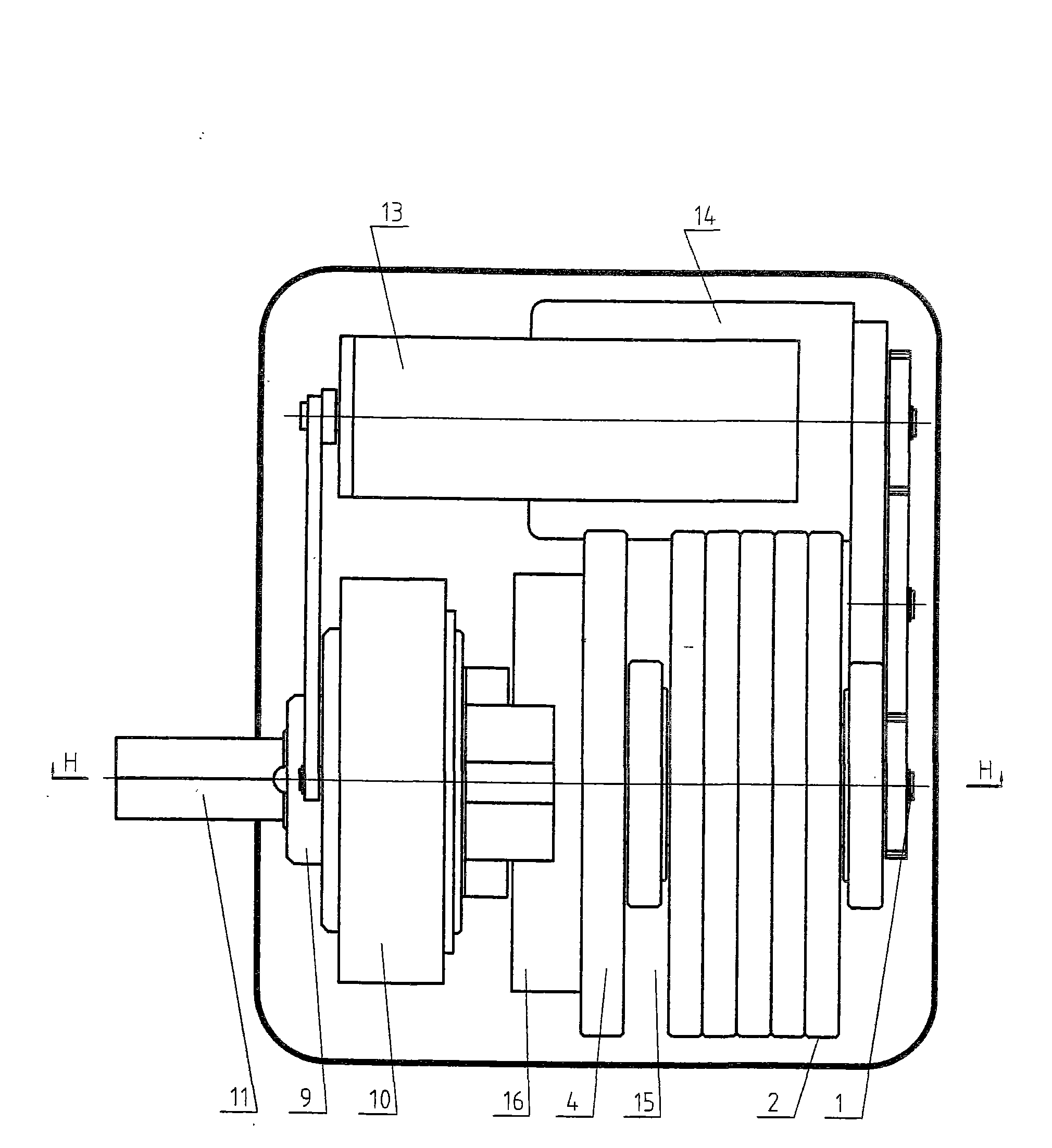
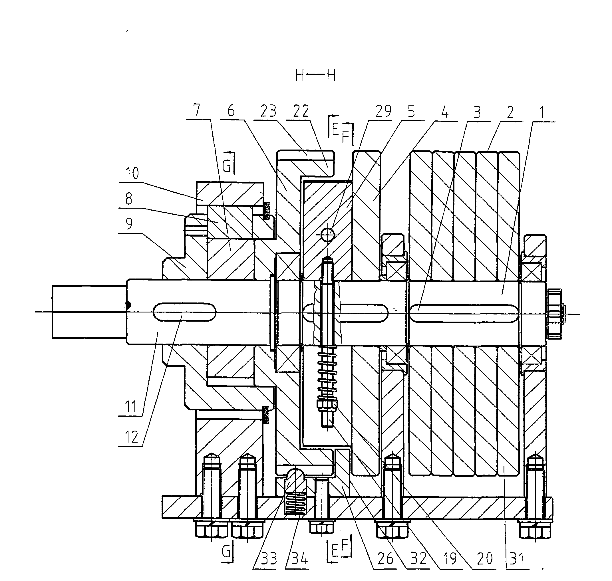
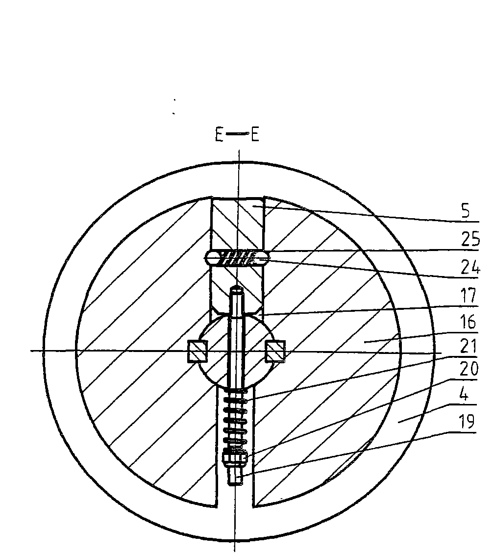
  • Combined electrical apparatus isolation earthing switch operating mechanism
  • Combined electrical apparatus isolation earthing switch operating mechanism
  • Combined electrical apparatus isolation earthing switch operating mechanism

Examples


Embodiment 1

[0057] Such as Figure 11 As shown, as an embodiment in which the output shaft 11 rotates 30° when two or three stations are used, the angles between the centerlines of two adjacent movable key mounting holes 28 are 150°, 60°, and 150° respectively.

Embodiment 2

[0059] Such as Figure 12 As shown, as an embodiment in which the output shaft rotates 45° when two or three stations are used, the angles between the centerlines of two adjacent movable key mounting holes 28 are 135°, 90°, and 135° respectively.

Embodiment 3

[0061] Such as Figure 13 As shown, as an embodiment in which the output shaft 11 rotates 60° during two-station, three-station or multi-station, the angles between the centerlines of two adjacent movable key mounting holes 28 are 120° and 120° respectively. , 120°.


PUM


Abstract

The invention relates to a combine electrical apparatus isolation earthing switch operating mechanism. A transmission shaft is provided with a cylindrical energy storage flywheel and a truncated cone-shaped striking flywheel which is internally provided with a flying block; an output shaft is provided with a transition wheel which is movably matched with the output shaft, a radial cam and a divided wheel which is fixedly connected with the output shaft; the transition wheel is fixedly connected with the radial cam by an end face D-pad; the flying block is intermittently connected with a till-shaped rotating hammer in a striking way; the radial cam drives the divided wheel and the output shaft by a loose key to rotate according to a stated angle; the low part of the transition wheel is provided with a release used for forcibly releasing the striking; the flying block is internally provided with a steel ball and a spring which can accelerate the flying block. The operating mechanism can realize different output angles of two work stations, three work stations, multistation 15 degrees-165 degrees and the like and is applied to the operation of 110kV, 220kV, and 550kV combined electrical apparatus isolation, earthing switches and isolation earthing combined switches, has the main advantages of high indexing accuracy, firm position locking, convenient regulation, low manufacturing cost, compact structure, low volume, extensive application, etc.

Description

technical field [0001] The invention relates to a switch operating mechanism, in particular to an isolating and grounding switch operating mechanism of a combined electric appliance. Background technique [0002] The action of the combined electrical isolation and grounding switch requires that the operating mechanism must have various performances: one is that there are two or two positions, three or three positions or multiple or multiple positions, and the working position of the switch. The second is to have a certain torque to ensure the action of the switch; the third is to have a certain speed of action to meet the movement characteristics of the switch; the fourth is to have an accurate output angle to ensure the working position of the switch and lock it. [0003] At present, combined electrical appliances with domestic and foreign technology are divided into two categories in terms of isolation and grounding switches: one is independent isolation and grounding swit...

Claims


Application Information

Patent Timeline
IPC IPC(8): H01H31/02H01H3/30
Inventor 魏巍
Owner 魏巍
Learn More