
High-viscosity fluid defoaming method and device thereof

A high-viscosity, fluid technology, applied in the direction of liquid degassing, separation methods, chemical instruments and methods, etc., can solve the problems of long degassing time, unable to meet the requirements of spinning process, unable to degassing and other problems

Inactive Publication Date: 2009-09-02
SHAOYANG TEXTILE MACHINERY
View PDF0 Cites 15 Cited by
  • Summary
  • Abstract
  • Description
  • Claims
  • Application Information

AI Technical Summary

Problems solved by technology

There is a fatal defect in these two defoaming methods. When the spinning fluid is a high-viscosity fluid (such as producing carbon fiber and aramid fiber 1414, the viscosity of the spinning fluid is as high as 200-500Pa·S). None of the methods can be realized, the reason is: when the static vacuum defoaming method is adopted, because the diffusion speed of the bubbles in the high-viscosity fluid is too slow, it takes a long time for the bubbles to move from the middle of the container to the liquid surface of the container under the action of vacuum negative pressure , so the defoaming time is very long, while the permissible residence time of some high-viscosity fluids such as carbon fiber, aramid 1414 and other spinning fluids is very short. Silk process requirements
When the slit overflow vacuum defoaming method is used, the surface tension of the spinning fluid on the wall of the barrel is too high to flow automatically. The shape flows down as a whole and cannot form a continuous film, so it cannot be defoamed

Method used


Image

  • High-viscosity fluid defoaming method and device thereof
  • High-viscosity fluid defoaming method and device thereof

Examples


Embodiment Construction

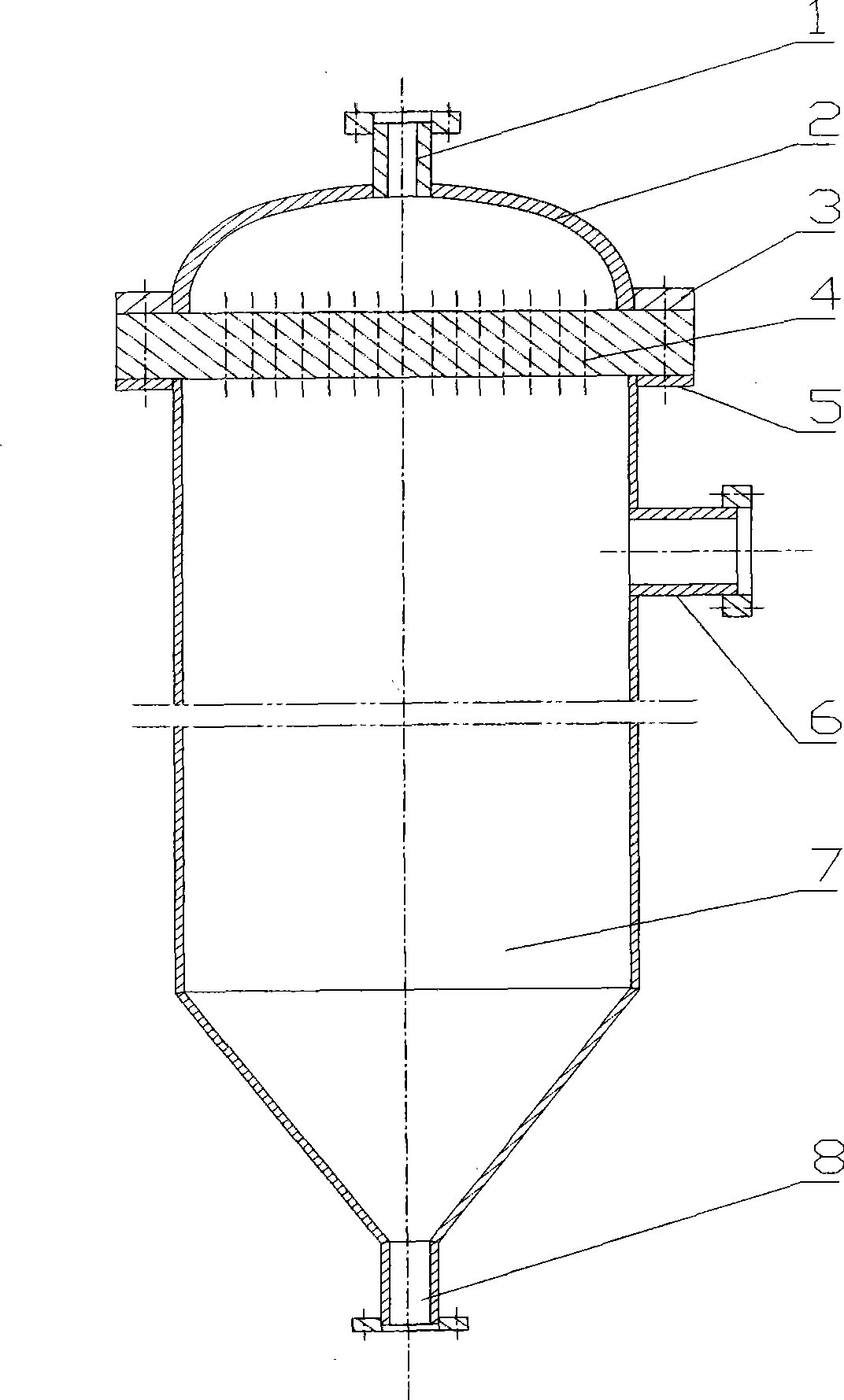
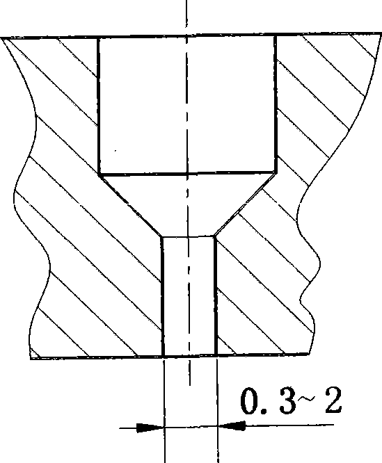
[0012] Such as figure 1 , 2 As shown, the embodiment of the present invention consists of feed inlet (1), end cap (2), upper flange (3), extruded film plate (4), lower flange (5), (6) vacuum suction port, vacuum It consists of a degassing tower (7) and a discharge port (8). The head (2) is located above the extruded plate (4), connected with the extruded plate (4) through the upper flange (3), and forms a fluid distribution chamber with the extruded plate (4). A feed port (1) is provided. The extruded film plate (4) is a circular disk, and it is provided with an oblong narrow hole penetrating up and down. The upper part of the narrow hole is wide, which is a fluid guide area, and the middle part has a slope, which is a tapered transition area. Film extrusion zone, the width of the film extrusion zone is 0.3-2 mm, and the aspect ratio of the film extrusion zone is about 5-15. The vacuum defoaming tower (7) is located directly below the extruded film plate (4), and is connec...


PUM


Abstract

The invention relates to a high-viscosity fluid defoaming method and a device thereof. The upper part of the device is a round tank; the lower part is a cone; a feed inlet is arranged on the upper side of an end enclosure; the lower side of the end enclosure is connected with a film-extruding plate by a flange; and the end enclosure forms a containing cavity along with the film-extruding plate; normally, the film-extruding plate is a round or square thick plate, on which a large quantity of long-circular narrow holes are arranged; the upper part of each hole is wide and is a fluid-guiding area; the middle part of the hole is sloped and is a tapered transitional area; and the lower part of the hole is narrow and is a film-extruding area. A vacuum defoaming tower is located right below the film-extruding plate and connected with the film-extruding plate by a flange; a vacuumizing inlet is arranged on the side of the vacuum defoaming tower; and a discharge outlet is arranged on the lower side of the vacuum defoaming tower. The high-viscosity fluid rapid defoaming method and the device thereof have the advantages of good defoaming effect, short deforming time and high output.

Description

Technical field [0001] The invention relates to a high-viscosity fluid rapid defoaming method and a device thereof in the field of chemical fiber spinning. Background technique [0002] At present, in the preparation process of wet spinning or dry-wet spinning (also known as dry-jet wet spinning), in order to improve fiber quality and reduce spinning breakage, the spinning fluid needs to be degassed to remove Small air bubbles in the spinning fluid. The usual defoaming methods are static vacuum defoaming method and slit overflow vacuum defoaming method. The static vacuum defoaming method is to put the fluid into a sealed container, generally make the volume of the fluid in the container account for 1 / 2 to 2 / 3 of the total volume of the container, and then evacuate the air in the upper part of the container, and the air bubbles in the fluid will expand due to vacuum And overflow the liquid surface, rupture. Static defoaming generally requires continuous vacuum for 12 to 36...

Claims


Application Information

Patent Timeline
IPC IPC(8): D01D1/10B01D19/00
Inventor 肖坤后刘顺同杨正锋吴继发
Owner SHAOYANG TEXTILE MACHINERY
Learn More