
Electromagnetic valve

A solenoid valve and valve port technology, applied in the field of solenoid valves, can solve problems such as increased material costs, increased cost of solenoid valves, increased iron core diameter, etc., to achieve miniaturization and reduce production costs

Active Publication Date: 2009-09-02
ZHEJIANG SANHUA INTELLIGENT CONTROLS CO LTD
View PDF0 Cites 5 Cited by
  • Summary
  • Abstract
  • Description
  • Claims
  • Application Information

AI Technical Summary

Problems solved by technology

In the prior art, the method of increasing the diameter of the iron core is usually used to solve the above problems. However, increasing the diameter of the iron core also increases the cost of materials correspondingly, thereby increasing the overall cost of the solenoid valve.

Method used

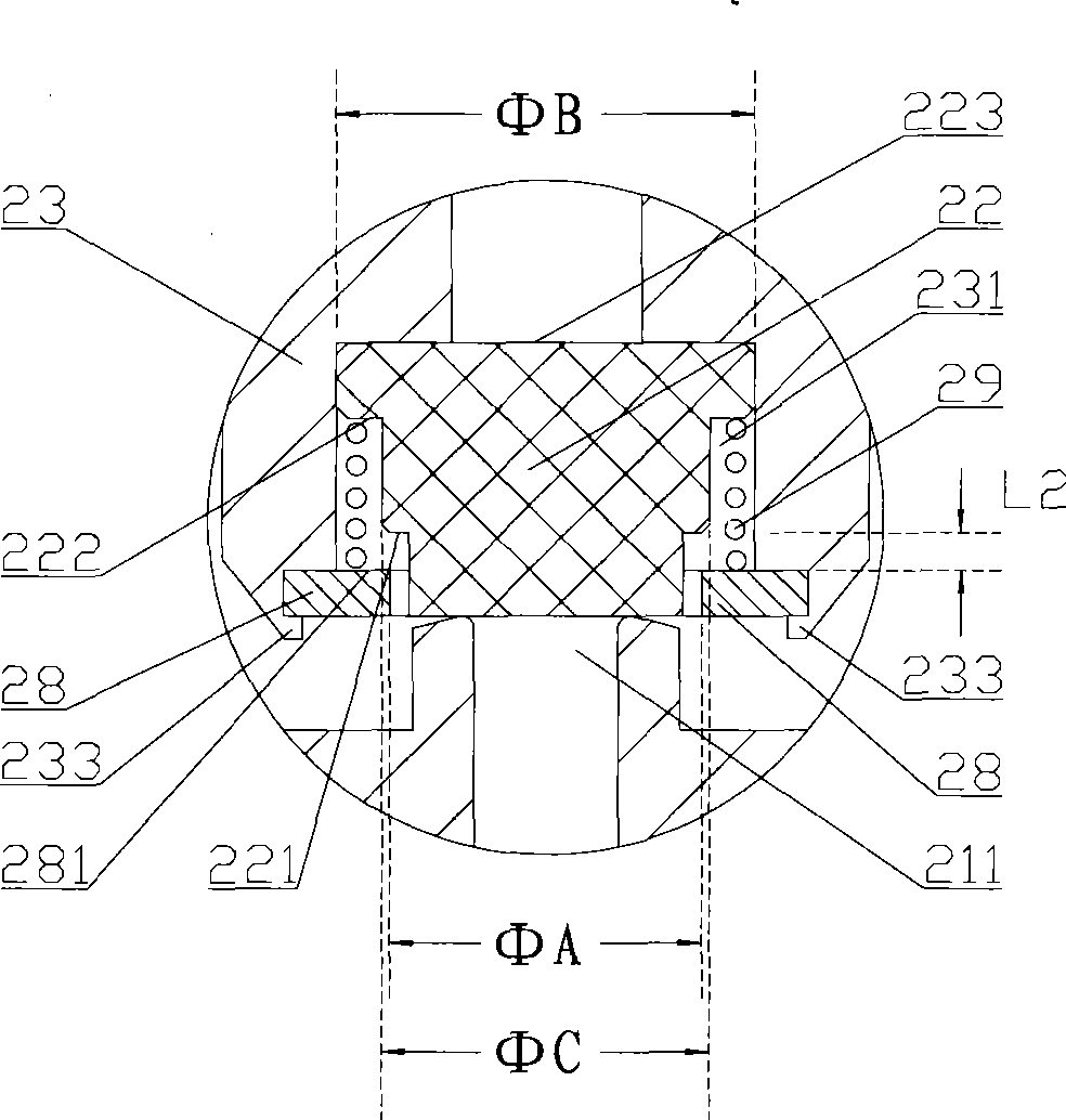

Image

  • Electromagnetic valve
  • Electromagnetic valve
  • Electromagnetic valve

Examples


Embodiment Construction

[0028] The core of the present invention is to provide a solenoid valve capable of overcoming a sufficiently large operating pressure difference, and having smaller specifications and lower manufacturing costs.

[0029] In order to enable those skilled in the art to better understand the solution of the present invention, the present invention will be further described in detail below in conjunction with the accompanying drawings and embodiments.

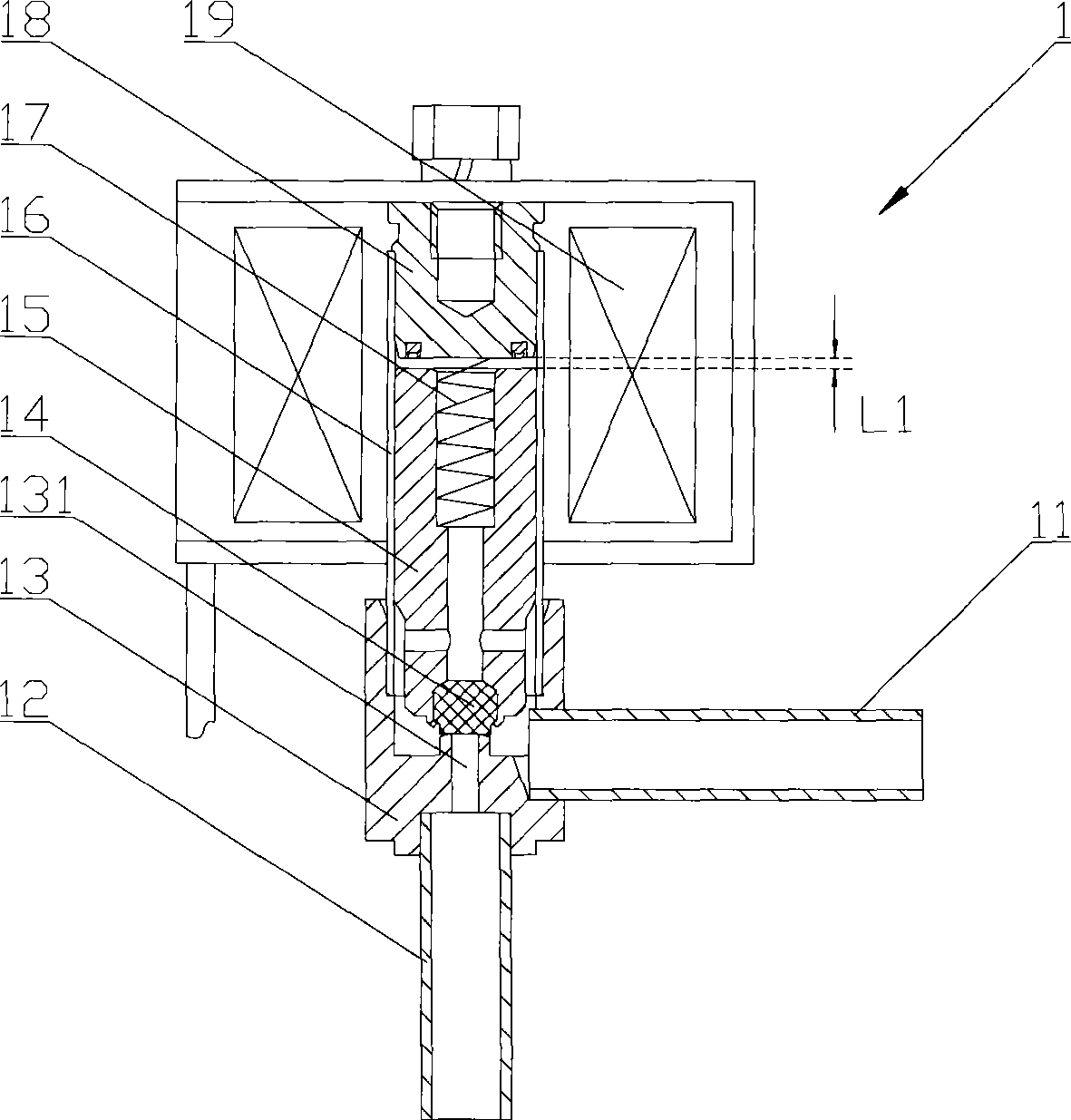
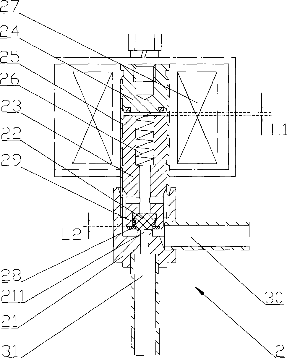
[0030] Please refer to figure 2 , figure 2 It is a structural schematic diagram of a specific embodiment of the electromagnetic valve provided by the present invention.

[0031] In a specific embodiment, the electromagnetic valve 2 provided by the present invention includes an inlet pipe 30 , an outlet pipe 31 and a valve seat 21 respectively communicating with the two, and the valve seat 21 has a valve port 211 .

[0032] A sealing plug 22 is arranged in the medium channel of the electromagnetic valve 2, and the sealing plug 22...


PUM


Abstract

The invention discloses an electromagnetic valve, a sealing plug (22) of which is movably clamped and connected in a central cavity (231) at the end part of core iron (23) and has a free stroke (L2) in the moving direction of the core iron (23). The free stroke (L2) is less than the stroke (L1) of the core iron in the open or close process of the electromagnetic valve. The core iron and the sealing plug of the electromagnetic valve are two mutually independent parts without interaction force, therefore the core iron has very small resistance in the process of starting movement and normal open or close can be realized by using a coil and core iron which are of small specification, thus being beneficial to the miniaturization of the electromagnetic valve and strikingly reducing the manufacture cost.

Description

technical field [0001] The invention relates to the field of control valves, in particular to a solenoid valve used in control systems such as HVAC and refrigeration. Background technique [0002] Solenoid valves are often used in HVAC, refrigeration and other systems involving temperature control and regulation to control the on-off of the medium in the piping system. [0003] Please refer to figure 1 , figure 1 It is a structural schematic diagram of a typical solenoid valve in the prior art. [0004] A typical solenoid valve 1 in the prior art includes an inlet pipe 11 and an outlet pipe 12 . The inlet pipe 11 communicates with the liquid inlet of the valve seat 13 , while the outlet pipe 12 communicates with the valve port 131 of the valve seat 13 . [0005] A sealing plug 14 is arranged in the medium passage of the solenoid valve 1, and the sealing plug 14 is fixedly connected to the end of the core iron 15, and the two are usually clamped; when the solenoid valve 1...

Claims


Application Information

Patent Timeline
Patent Type & Authority Applications(China)
IPC IPC(8): F16K31/06F16K1/36F16K27/02F25B41/04
Inventor 严卫林王大闯
Owner ZHEJIANG SANHUA INTELLIGENT CONTROLS CO LTD
Learn More