
Method and device for testing microcomputer control system of diesel locomotive

A technology of microcomputer control and system testing, applied in the direction of electrical testing/monitoring, etc., to achieve the effects of small size, improved vehicle simulation test, and strong versatility

Inactive Publication Date: 2009-09-02
ZHUZHOU CSR TIMES ELECTRIC CO LTD
View PDF0 Cites 20 Cited by
  • Summary
  • Abstract
  • Description
  • Claims
  • Application Information

AI Technical Summary

Problems solved by technology

[0004] In order to overcome the fact that the existing microcomputer control system testing devices of diesel locomotives cannot well meet the needs of current testing, the present invention provides a new testing method and device for microcomputer control systems. System automatic testing and debugging needs to improve the overall level of diesel locomotive products; and the appearance is very beautiful, small in size, light in weight, easy to test directly on the locomotive, and adopts modular design to facilitate function expansion

Method used


Image

  • Method and device for testing microcomputer control system of diesel locomotive
  • Method and device for testing microcomputer control system of diesel locomotive
  • Method and device for testing microcomputer control system of diesel locomotive

Examples


Embodiment Construction

[0018] The present invention will be further described below with reference to the accompanying drawings.

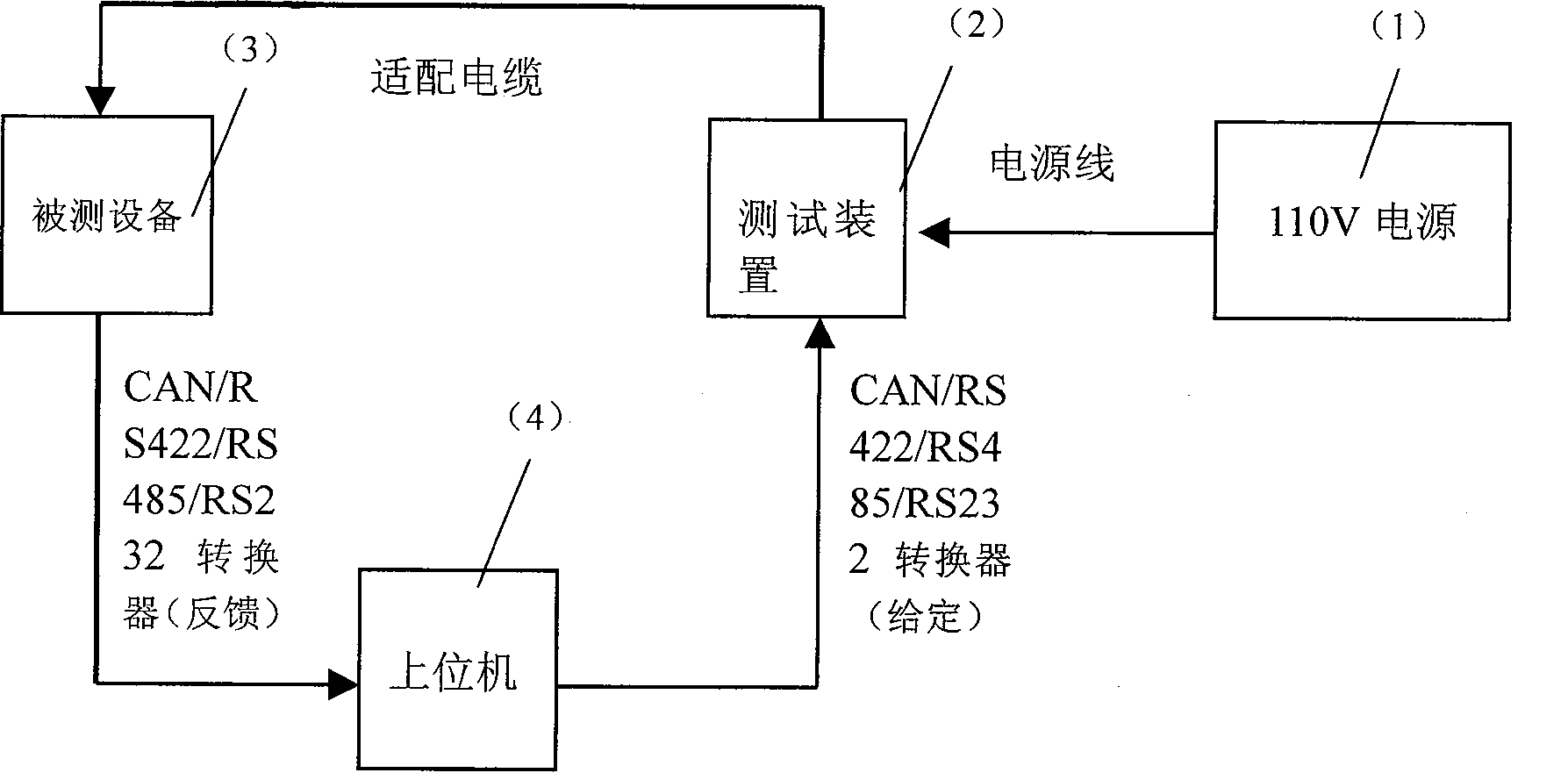
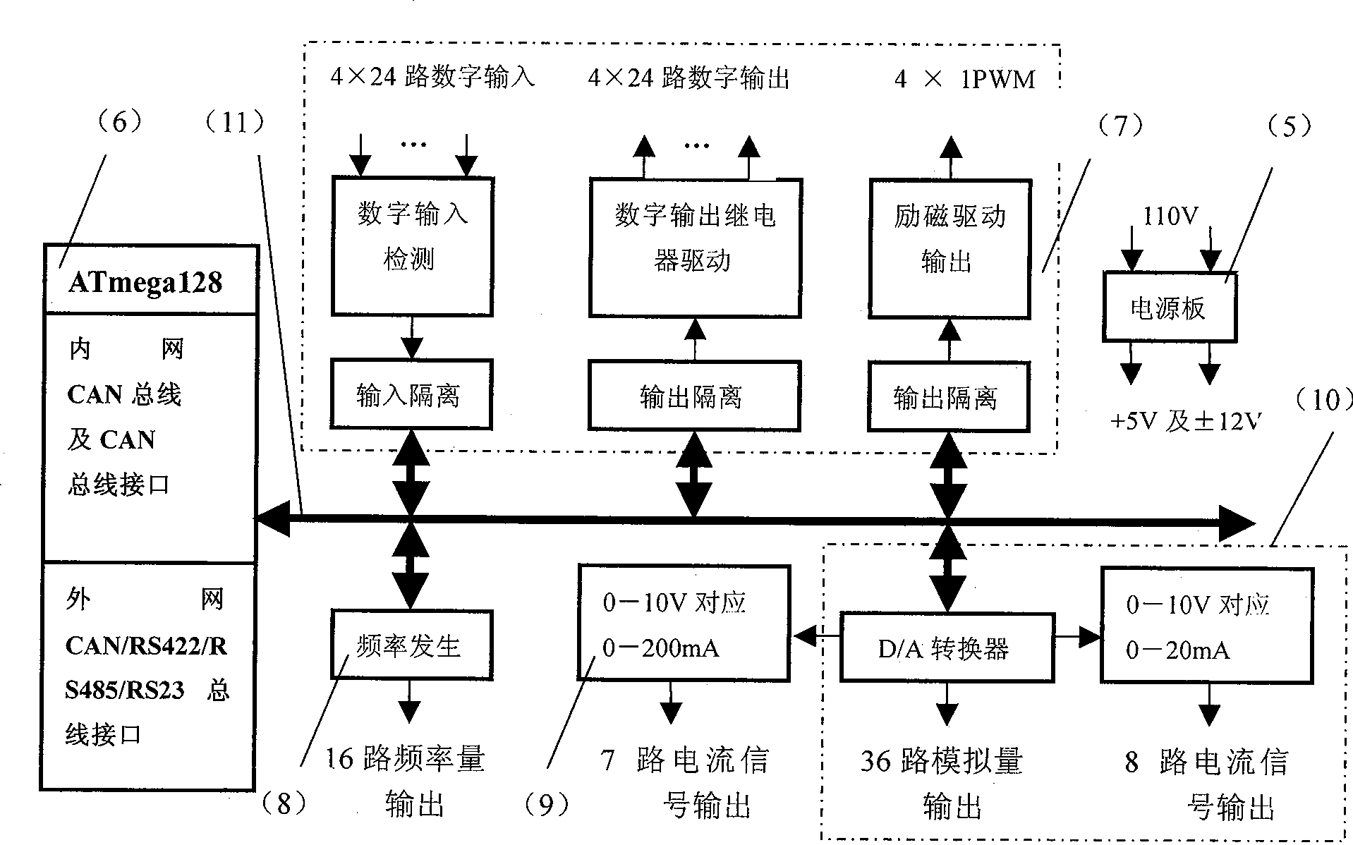
[0019] attached figure 1 It is a block diagram of the entire test system composed of the test device, the host computer, and the equipment under test. figure 1 It can be seen that the present invention is a test system for a microcomputer control system of a diesel locomotive. The whole system is composed of a 110V power supply 1 , a test device 2 , a device under test 3 and a host computer 4 . Among them, the 110V power supply 1 provides working power to the test device 2 and the device under test 3; the host computer 4 gives the command information and sends it to the test device 2 through CAN or serial bus (RS232, RS422, RS485, etc.); the test device 2 Provide various signal sources (such as digital input, digital output, analog voltage, current, etc.) to the device under test 3 through the adapter cable; the device under test 3 receives the corresponding signal, thr...


PUM


Abstract

The invention discloses a method and a device for testing a microcomputer control system of a diesel locomotive. A CAN bus or a serial bus is used for communication with an host computer to receive a test command from the host computer, and an inter CAN bus is used to receive the test command and transmits the test command to internal signal generation modules which generate a corresponding test signal according to the test command and transmit the test signal to equipment to be tested through an adapter cable; a signal detection module of a testing device detects an output signal of the equipment to be tested and transmits the output signal to a CPU board through the CAN bus, and the CAN bus or serial bus transmits the output signal to the host computer; and the host computer compares a given signal with the detected signal to realize the fully automatic closed loop test of the equipment to be tested. The fully automatic closed-loop test is a fully automatic loop test of the equipment to be tested which is implemented in a way that: the inside of the testing device adopts a distribution type module based on the CAN bus, the CPU board is connected with a digital quantity input and output board, a frequency board, a constant-current source board and a DA board through the internal CAN bus, and the testing device uses the external CAN bus or serial bus of the CPU board to communicate with the host computer and to realize the automatic circulating test of the equipment to be tested.

Description

Technical field [0001] The invention relates to a microcomputer control system testing method and device for a locomotive, in particular to a microcomputer control system testing method and device for a diesel locomotive based on a microcomputer network control system. Background technique [0002] The existing diesel locomotive microcomputer control system test devices are various in road bureaus and manufacturers, and they are basically test devices for specific models (diesel locomotives DF11 and DF8B series, etc.) and single-board testing of the equipment under test. The original design principle of the test device is basically composed of a potentiometer, a switch button, an indicator light, a frequency generator, a constant voltage and constant current source and other signal sources. Various test signals are manually given through potentiometers and switch buttons, and they are all open-loop control tests and individual test benches have some microcomputer functions. ...

Claims


Application Information

Patent Timeline
Patent Type & Authority Applications(China)
IPC IPC(8): G05B23/02
Inventor 周少云吴正平何良任湘辉施洪亮肖孟英肖健刘松柏
Owner ZHUZHOU CSR TIMES ELECTRIC CO LTD
Learn More