Solidification microstructure of aggregate molded shaped castings

A microstructure and casting technology, applied in the direction of manufacturing tools, casting equipment, metal processing equipment, etc., can solve the problem of damage to the ductility of the alloy

Active Publication Date: 2009-09-02
ALOTECH LTD +1
View PDF1 Cites 6 Cited by
  • Summary
  • Abstract
  • Description
  • Claims
  • Application Information

AI Technical Summary

Problems solved by technology

All these factors greatly detrac

Method used


Image

  • Solidification microstructure of aggregate molded shaped castings
  • Solidification microstructure of aggregate molded shaped castings
  • Solidification microstructure of aggregate molded shaped castings

Examples


Embodiment

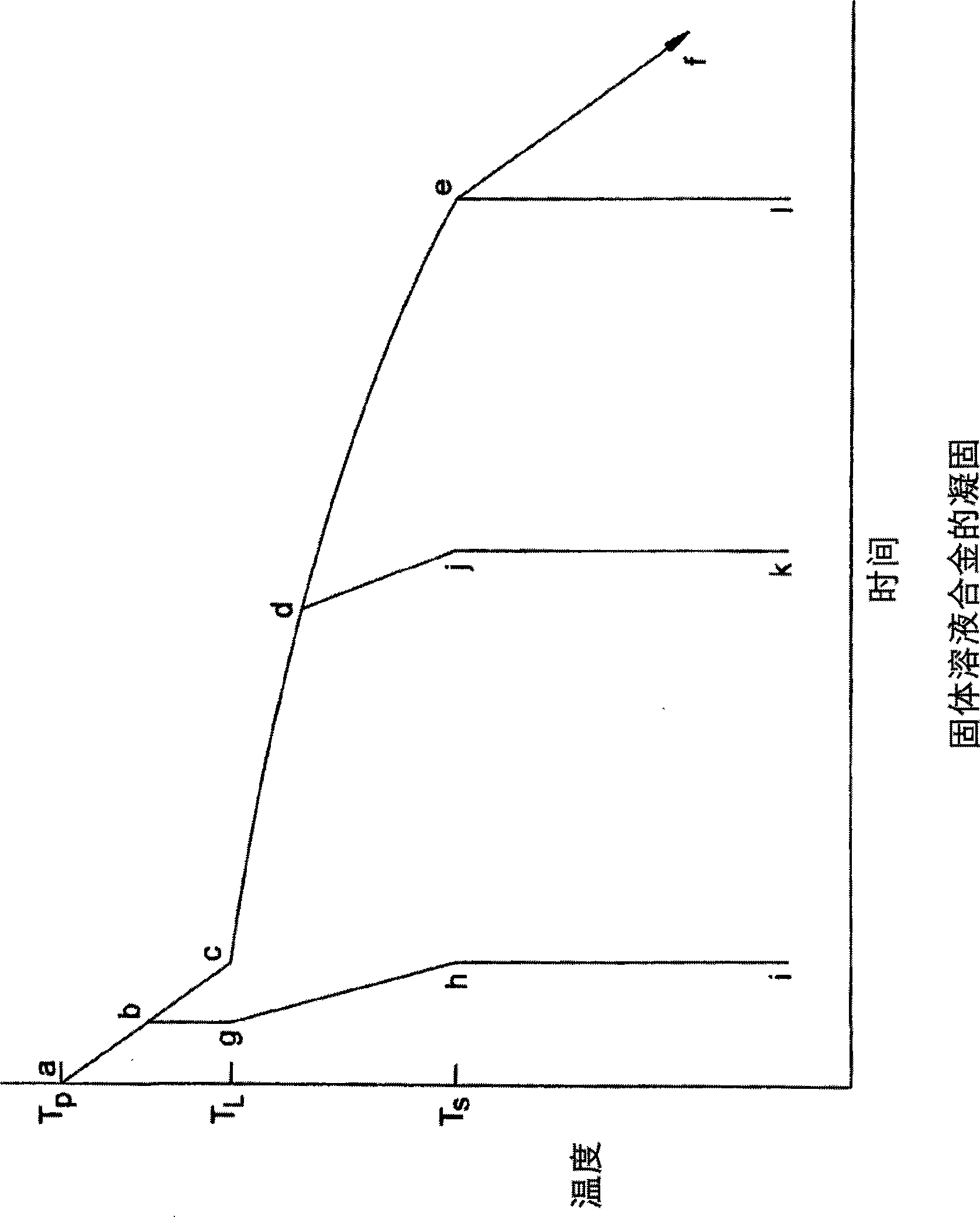
[0091] In one example of the application of the technology described in this application, a single test bar of 20 mm in diameter and 200 mm in length was molded, equipped at one end with a small conical sprue cup filled to act as a feeder . The model material was silica molding sand bound with a water-soluble inorganic binder as described in co-pending application Ser. No. 10 / 614,601.

[0092] A thermocouple was inserted into the mold cavity at the base of the feeder, at the base of the mold cavity. Place two additional thermocouples at equal intervals along the axis. The four thermocouples are labeled TC1 (riser), TC2 (top middle), TC3 (bottom middle), and TC4 (bottom).

[0093] A 6061 aluminum alloy at a temperature of 730°C (1350°F) was poured into a mold cavity positioned perpendicular to its axis. Water at 20°C (68°F) was then applied from a nozzle directed at the base of the model over a period of about 10 seconds, starting ablation of the model upwards from the base....


PUM


Abstract

A shaped metal casting made in an aggregate mold comprises fine solidification microstructure that is finer than the solidification microstructure of an analogous metal casting made from conventional molding processes. The solidification microstructure may be up to five times finer than the solidification microstructure of a conventionally prepared casting. In preferred embodiments, as a result of directional solidification, the fine solidification microstructure is substantially continuous from a distal end of the casting to a proximal end of the casting, and exhibits greatly enhanced soundness. Because of the control of the uniformity of freezing of the casting, its properties are substantially uniform.

Description

technical field [0001] This invention relates to metal castings. More specifically, the present invention relates to aggregate formed metal castings having a fine solidified microstructure. Background technique [0002] In conventional casting methods, molten metal is poured into a mold and solidifies or freezes due to the loss of heat from the mold. When enough heat has been lost from the metal so that the metal has solidified, the resulting product, the casting, can support its own weight. The casting is then removed from the mold. [0003] Different types of models of the prior art have certain advantages. For example, green sand molds consist of aggregates, molding sand, held together by a binder such as a mixture of clay and water. Such models can be manufactured rapidly, eg, within ten (10) seconds for simple models, in an automated model making plant. In addition, molding sand can be recycled relatively easily for further use. [0004] Other sand molds generally...

Claims


Application Information

Patent Timeline
IPC IPC(8): B22D25/00B22D25/06
CPCB22D15/04B22D46/00B22D21/007B22D27/04B22D30/00B22D25/06B22D15/00C22C21/00C22F1/002C22F1/04
Inventor 约翰·R·格莱斯约翰·坎贝尔J·福瑞德·玫杰
Owner ALOTECH LTD
Why Eureka
Try Eureka