
Control method and device for continuous metal monocrystal casting process

A single crystal, metal technology, applied in the field of process parameters in the process of metal single crystal continuous casting, can solve problems such as process conditions that are not mentioned

Inactive Publication Date: 2006-08-02
上海智诚电讯材料有限公司
View PDF2 Cites 29 Cited by
  • Summary
  • Abstract
  • Description
  • Claims
  • Application Information

AI Technical Summary

Problems solved by technology

DOWA Mining uses vacuum high-frequency heating for smelting, but does not mention the specific process conditions of the infusion and drawing process

Method used


Image

  • Control method and device for continuous metal monocrystal casting process
  • Control method and device for continuous metal monocrystal casting process
  • Control method and device for continuous metal monocrystal casting process

Examples


Embodiment Construction

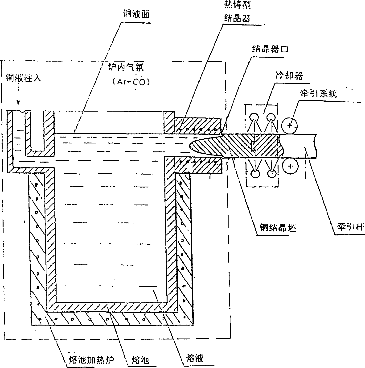
[0030] The structure of the complete horizontal directional solidification continuous casting device of one embodiment of the present invention is as follows: Figure 4 As shown, the device consists of three chambers separated by two vacuum isolation valves V1 and V2, namely the feeding chamber 1, the melting chamber 3 and the continuous casting chamber 5 and their cooling and pulling systems, and the configuration for each chamber Composed of pumping and argon filling system. The device realizes vacuum feeding intermittent smelting feeding and long-term continuous drawing casting.

[0031] The technical process of preparing single crystal copper by adopting the single crystal horizontal continuous casting device of the present invention is as follows Figure 5 shown. The present invention adopts vacuum feeding, vacuum intermediate frequency heating and smelting, liquid infusion in argon atmosphere, heat preservation and continuous casting, that is, the whole process of feed...


PUM


Abstract

The metal monocrystal casting device consists of three work chambers formed with two vacuum isolating valves and their cooling and drawing system integrated together. The horizontal oriented solidifying continuous casting process are performed in a protecting atmosphere so as to obtain copper monocrystal with very low content of O, H and other impurity.

Description

technical field [0001] The invention relates to the process parameters in the metal single crystal continuous casting process, mainly the stable control of the protective atmosphere of the melt, the height of the metal liquid level, the temperature of the casting billet at the crystallizer die, the position of the solid-liquid interface, etc., and related equipment. The present invention particularly relates to the realization of horizontal continuous casting of single crystal copper by using the above control method and equipment. technical background [0002] Single crystal continuous casting technology is the combination of directional solidification technology and continuous casting technology to realize the continuous casting of metal single crystal. This technology is mainly used to prepare single crystals of metals (high-purity metals and alloys), and it can also prepare difficult-to-machine metal profiles and metal profiles with complex cross-sections. Single crysta...

Claims


Application Information

Patent Timeline
IPC IPC(8): B22D27/04B22D11/11
Inventor 解洪湛毛协民徐建泉谭儒环金雁声解洪浩
Owner 上海智诚电讯材料有限公司
Learn More