Wheel set shaft for an electric drive unit mounted on the axle and drive unit

A wheel-to-axle and motor technology, applied in the field of wheel-to-axle, can solve the problems of increasing manufacturing cost, high cost, etc., and achieve the effect of reducing types

Inactive Publication Date: 2009-09-02
SIEMENS AG
View PDF0 Cites 6 Cited by
  • Summary
  • Abstract
  • Description
  • Claims
  • Application Information

AI Technical Summary

Problems solved by technology

These measures are expensive and will increase manufacturing costs

Method used


Image

  • Wheel set shaft for an electric drive unit mounted on the axle and drive unit
  • Wheel set shaft for an electric drive unit mounted on the axle and drive unit
  • Wheel set shaft for an electric drive unit mounted on the axle and drive unit

Examples


Embodiment Construction

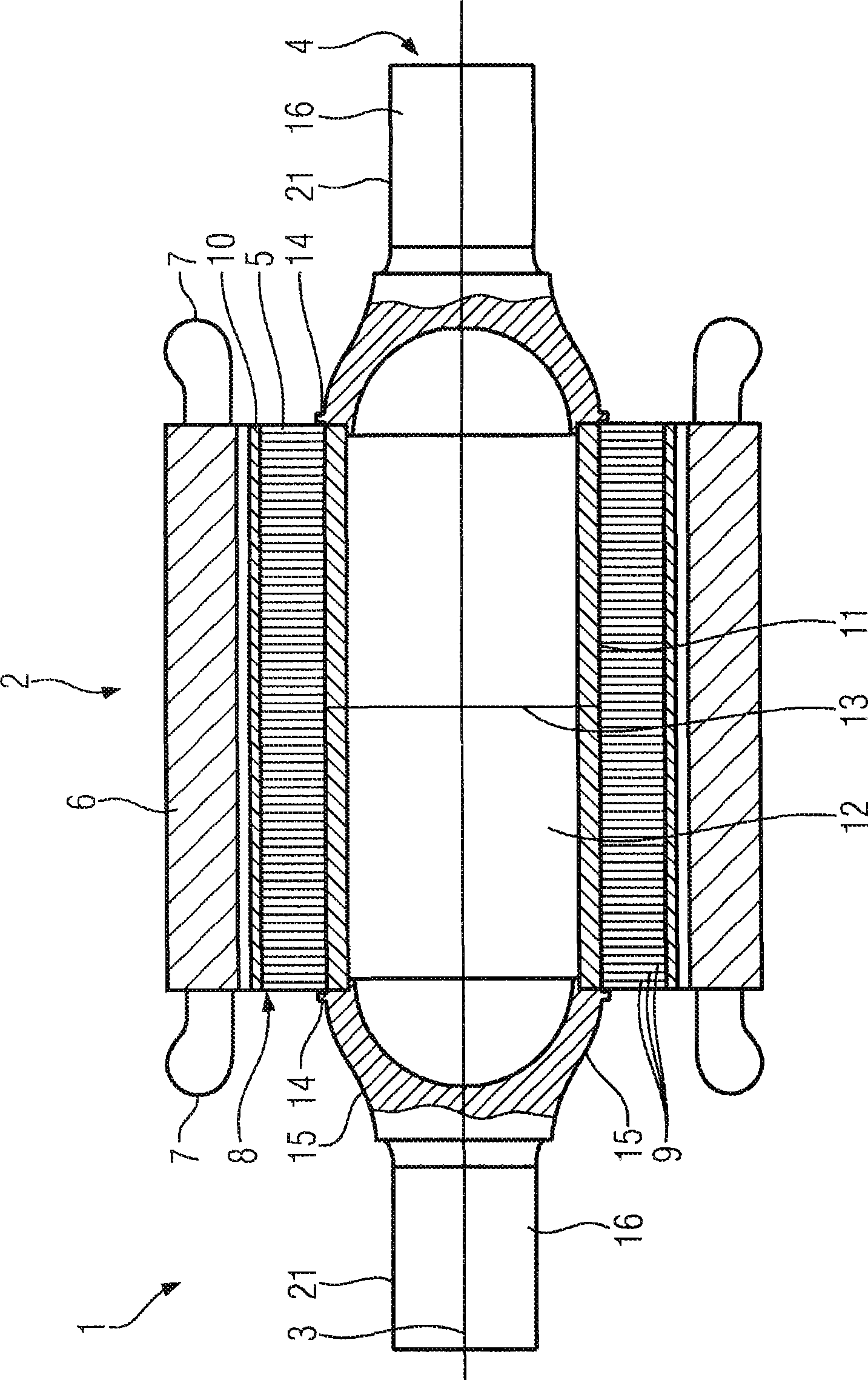
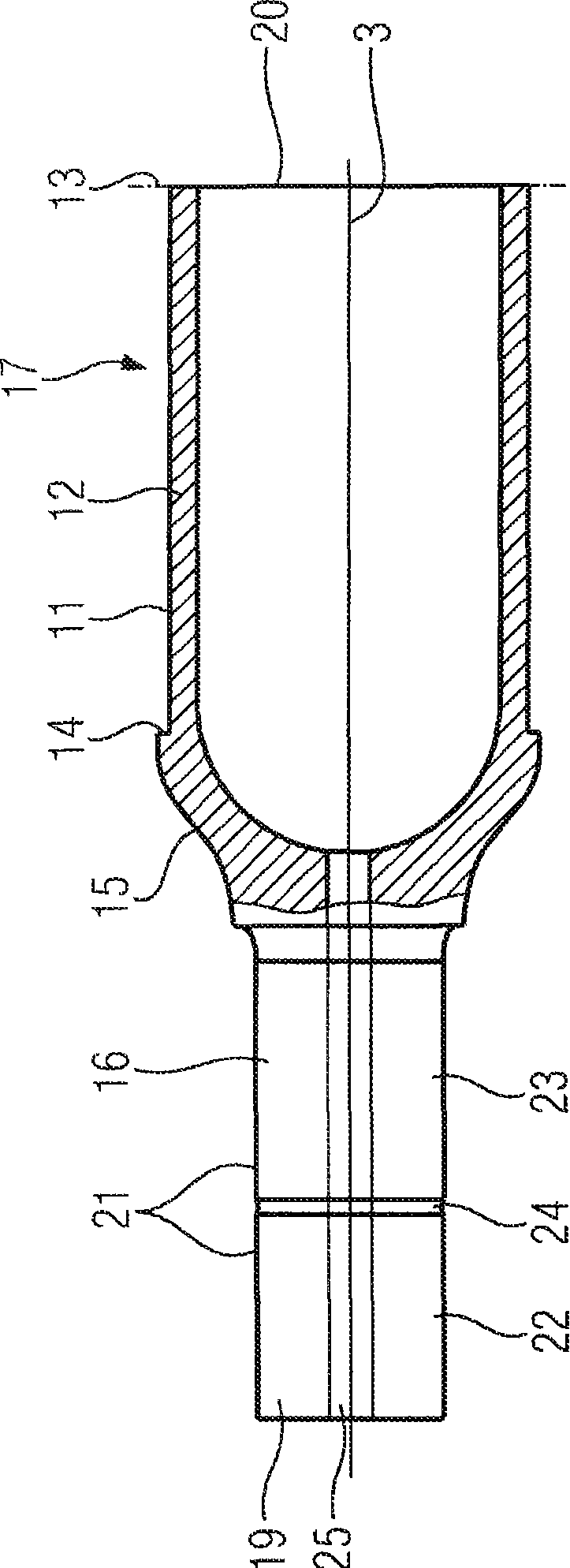
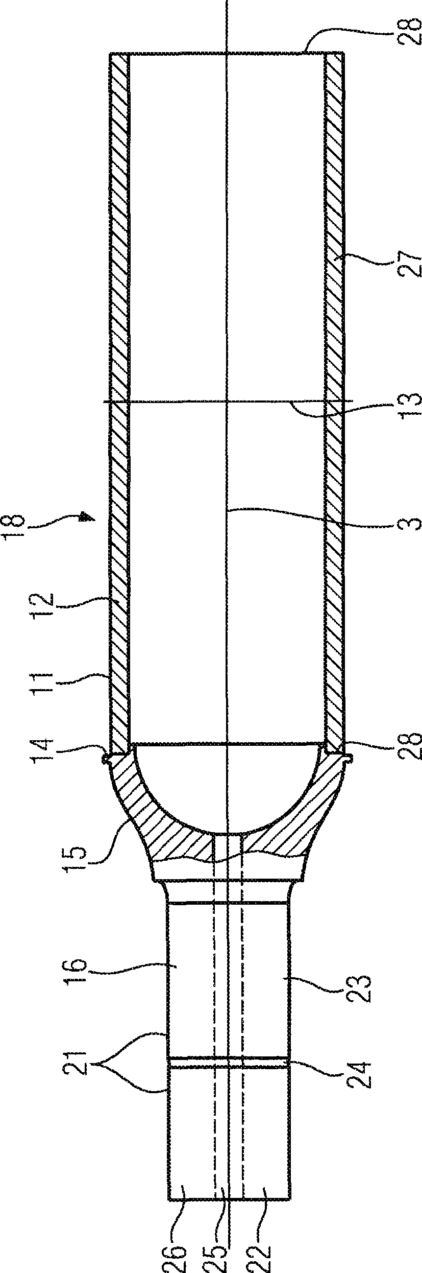
[0022] same parts in Figure 1 to Figure 3 are indicated by the same reference symbols.

[0023] figure 1 Shown is an exemplary embodiment of a gearless drive unit 1 with an electric motor 2 and a wheel shaft 4 driven to rotate about a rotational axis 3 . In this embodiment, the motor 2 is a permanent magnet synchronous motor, the rotor 5 of which is directly mounted on the wheel set shaft 4 . That is to say, the drive unit 1 is a gearless shaft-mounted non-flexible wheel set direct drive. This type of drive is mainly used in figure 1 on rail vehicles not shown in detail.

[0024] The motor 2 basically adopts a common structure. In addition to the rotor 5, the electric motor 2 also includes a stator 6 with a winding system, figure 1 Only the two axial end windings 7 of this winding system are shown schematically. The rotor 5 includes a stack of laminations 8 which has a plurality of punched laminations 9 stacked one after the other along the axial direction. A pluralit...


PUM


Abstract

The wheel set shaft (4) is intended for an electric drive unit mounted on the axle (2). It comprises two axially lateral edge regions (15, 16) and a center region (12) disposed between the edge regions (15, 16). Each edge region (15, 16) is at least partially designed substantially as a full cylinder having a first outer circumferential surface (21) for mounting a wheel or a bearing. The center region (12) is designed as an empty hollow cylinder having a second outer circumferential surface (11) for the direct mounting of a rotor (5) of the electric drive unit (2) mounted on the axle. Thus, the manufacturing effort and the overall weight are reduced, while at the same time ensuring high mechanical stability.

Description

technical field [0001] The invention relates to a wheel axle for an electric motor mounted on an axle, which comprises two axial side edge regions and a central region arranged between the edge regions. Furthermore, the invention relates to a drive unit with such a wheel-to-axle. Background technique [0002] M. Kaufhold (M. Kaufhold) and A. The technical paper "Permanenterregte Groβmaschinen: Potenziale in der Oberklasse (Large Permanent Magnet Motor: Potential in Top Configuration)" (2002, No. 20, pp. 2-7) by (A. Joker) et al. Traction drives for rail vehicles should be implemented as permanent magnet synchronous motors in the future, whether as flexible motors or as non-compliant motors (ie shaft-mounted motors). [0003] In this gearless inflexible wheel set direct drive, the rotor of the synchronous motor is mounted directly on the wheel set shaft via a rotor support tube. The rotor is supported on the wheel shaft, which is therefore at the same time the rotor shaft...

Claims


Application Information

Patent Timeline
Patent Type & Authority Applications(China)
IPC IPC(8): B61C9/38B60B37/04B60K1/00
CPCB61C9/38B60K1/00B60B2360/102B60B2310/208H02K1/28B60Y2200/30B60Y2200/912H02K7/003H02K1/278B60B37/04B60B2310/302Y02T30/10B60B35/12Y02T10/86Y02T30/00
Inventor 安德烈亚斯·约克尔马克西米利安·西蒙马丁·泰希曼
Owner SIEMENS AG
Why Eureka
Try Eureka