Safety valve of accelerator pedal motor vehicle

An accelerator pedal, motor vehicle technology, applied in the direction of motor vehicles, safety devices of power plant control mechanisms, tractors, etc., can solve the problems of inability to brake suddenly, step on the accelerator by mistake, etc., and achieve the effect of saving precious time

Inactive Publication Date: 2009-09-09
胡义平
View PDF2 Cites 9 Cited by
  • Summary
  • Abstract
  • Description
  • Claims
  • Application Information

AI Technical Summary

Problems solved by technology

At present, most of the inventions of the accelerator safety device on the car cannot achieve the effect of emergency braking at the moment when the driver steps on the accelerator by mistake, but there will be a process of continuing the downward oil supply of the pedal
For example: (200410015592.0) (200510030055.8), etc. In order to solve the problem of novice or non-professional drivers stepping on the accelerator by mistake, the usual practice is to strengthen the driver's emergency response ability
And this cannot completely avoid the misoperation of mistakenly using the accelerator as the brake in an emergency

Method used


Image

  • Safety valve of accelerator pedal motor vehicle
  • Safety valve of accelerator pedal motor vehicle
  • Safety valve of accelerator pedal motor vehicle

Examples


Embodiment 1

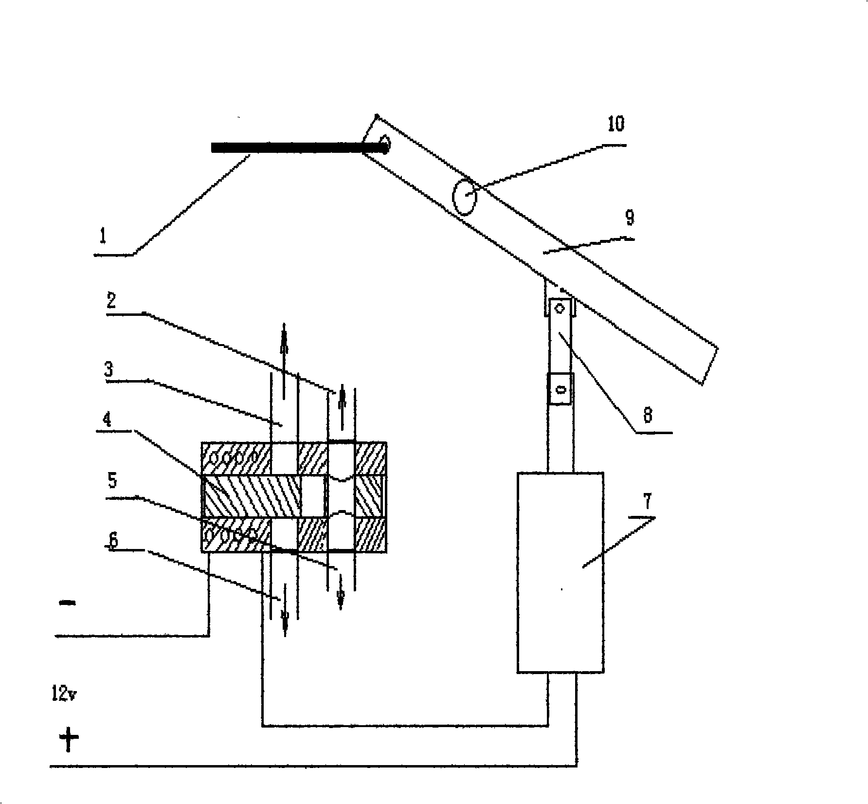
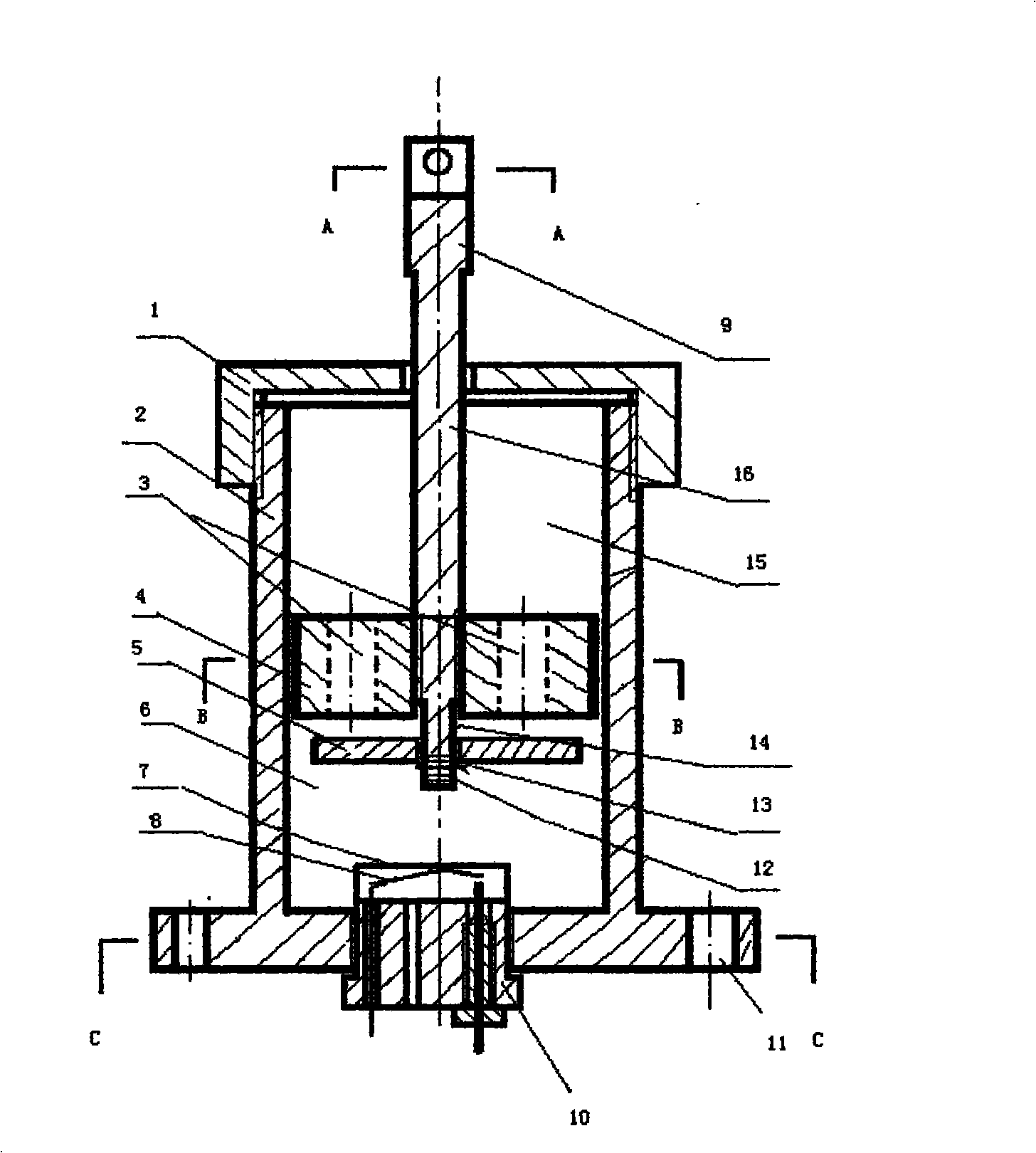
[0021] Combine below figure 1 and figure 2 Describe in detail the details and working conditions of the first embodiment according to the present invention. The liquid medium in this embodiment is an aqueous solution added with 30% ethylene glycol, the material of the valve plate 5 is brass, and the cylinder body 2 and the piston 4 are cast from aluminum alloy and then finished.

[0022] figure 2 It includes a cylinder body 2, and the cylinder body 2 and the cylinder body cover 1 are threaded. There is a piston 4 and a piston rod 16 linked with the accelerator pedal in the cylinder body 2. The piston 4 can slide freely on the inner wall of the cylinder body. The grinding precision of the mating surface should not be lower than 7. The smoothness of the contact surface between the valve plate 5 and the piston 4 is not less than 5 or Ra3.2 to ensure that the medium in the cylinder does not leak from the fitting when the pressure is higher than three atmospheres. The diam...

Embodiment 2

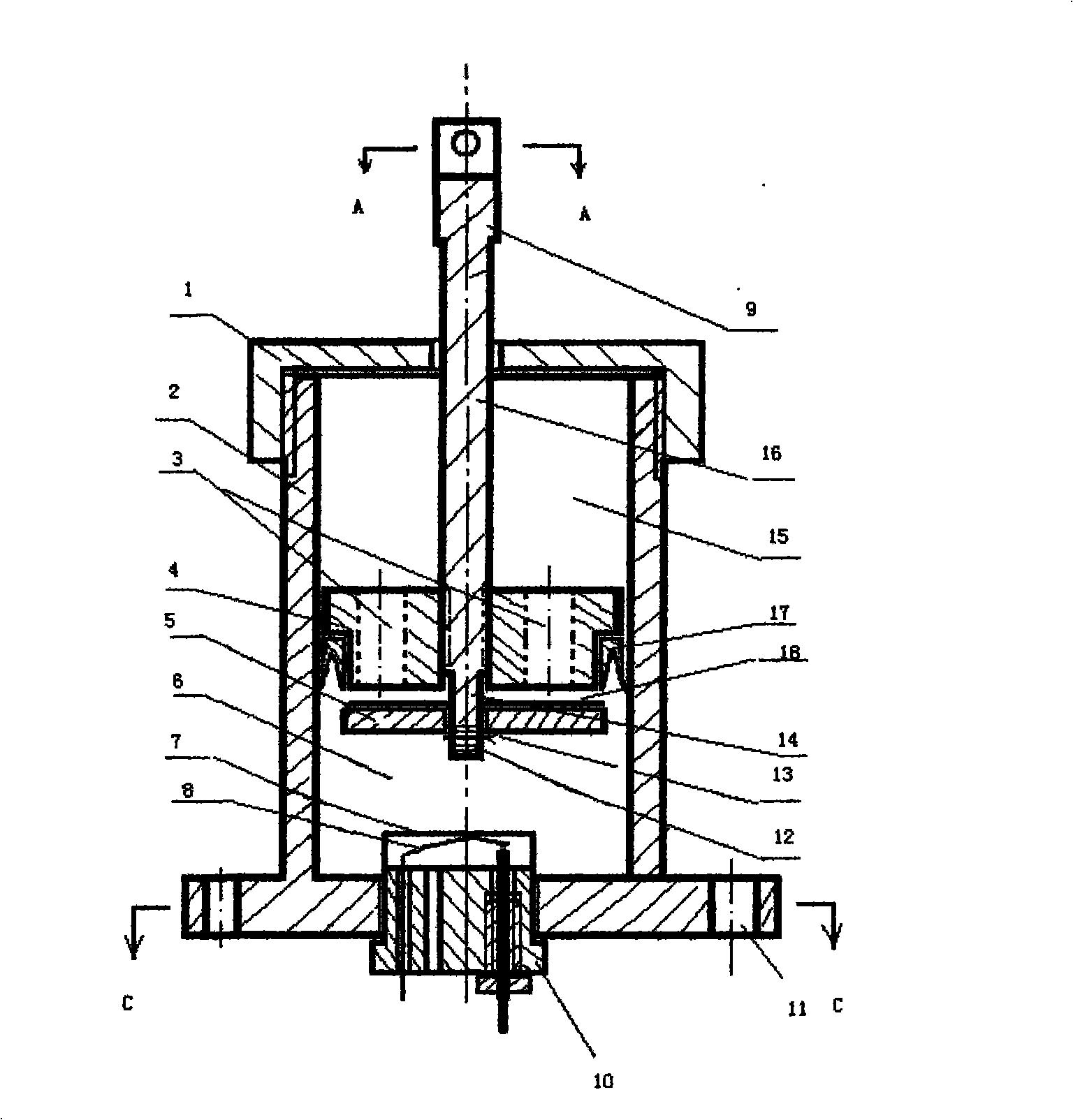
[0024] Combine below image 3 The important details and working conditions of Embodiment 2 proposed according to the present invention will be described. Apron 17 and soft rubber pad 18 are added in the present embodiment, and the radial dimension d of apron 17 is not greater than 10%-20% of the internal diameter of the cylinder. The axial dimension D is 1 / 2-1 of the thickness of piston 4 / 3. The soft rubber pad 18 covers the entire sealing surface of the pasted valve plate, and the thickness is 0.5mm. The middle part of the outer circumference of the piston 4 is processed with the installation position of the apron 17. After adding the apron 17 and the soft rubber pad 18, the piston 4 can still slide freely on the inner wall of the cylinder body 2, and the machining accuracy of the inner wall of the cylinder body 2 is not lower than 5. The machining accuracy of the mating surface of the piston 4 can be two grades lower than that of the inner wall of the cylinder body 2, and...


PUM


Abstract

The invention relates to a device for emergently and safely braking an accelerator of a motor vehicle. The device is characterized by comprising an accelerator operating rod, an accelerator pedal safety valve, a pressure sensor and an electromagnetic brake; the accelerator pedal safety valve is a columnar cylinder body filled with liquid; a piston and a piston rod can move between two ends of the cylinder body; liquid medium can flow via a through hole in the piston; one end of the through hole is provided with a corresponding valve plate; the piston rod is movably connected with the accelerator operating rod; a baroreceptor is arranged in the accelerator pedal safety valve and when a driver steps the accelerator by mistake in an emergency, the valve can close the through hole in the piston automatically and instantaneously so as to support and fix the accelerator operating rod tightly; and simultaneously the pressure change of the liquid excites an automatic braking system by the baroreceptor so as to achieve the purpose of emergency brake.

Description

technical field [0001] The invention relates to a motor vehicle, especially a safety protection device between a pedal oil feeder and a brake pad of a motor vehicle with a self-weight of less than 3 tons. Background technique [0002] The pedal accelerator and the brake of the existing motor vehicle are all arranged separately and operated separately. In an emergency, the operator often releases the accelerator first and then slams on the brakes. At this time, if the accelerator is mistakenly operated as a brake, a major traffic accident will be caused. At present, most of the inventions for the accelerator safety device on the car cannot achieve the emergency braking effect when the driver mistakenly steps on the accelerator, but there will be a process in which the pedal continues to descend to supply oil. For example: (200410015592.0) (200510030055.8) etc. In order to solve the problem of especially novice or non-professional drivers stepping on the accelerator by mista...

Claims


Application Information

Patent Timeline
Patent Type & Authority Applications(China)
IPC IPC(8): B60K28/14B60T7/12
Inventor 胡义平
Owner 胡义平
Why Eureka
Try Eureka