
Synchronous rectification external drive proposal

An external drive, synchronous rectification technology, applied in the direction of converting AC power input to DC power output, output power conversion devices, electrical components, etc. High, low cost, simplified drive design effect

Inactive Publication Date: 2009-09-09
李成勇
View PDF3 Cites 20 Cited by
  • Summary
  • Abstract
  • Description
  • Claims
  • Application Information

AI Technical Summary

Problems solved by technology

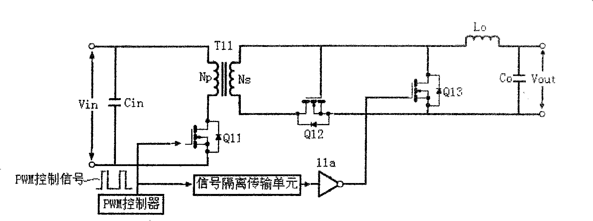
The Vout output is fed back, and the Vout output has a large reverse overshoot negative voltage. This situation is very easy to damage the load connected to the output terminal or cause logic errors.
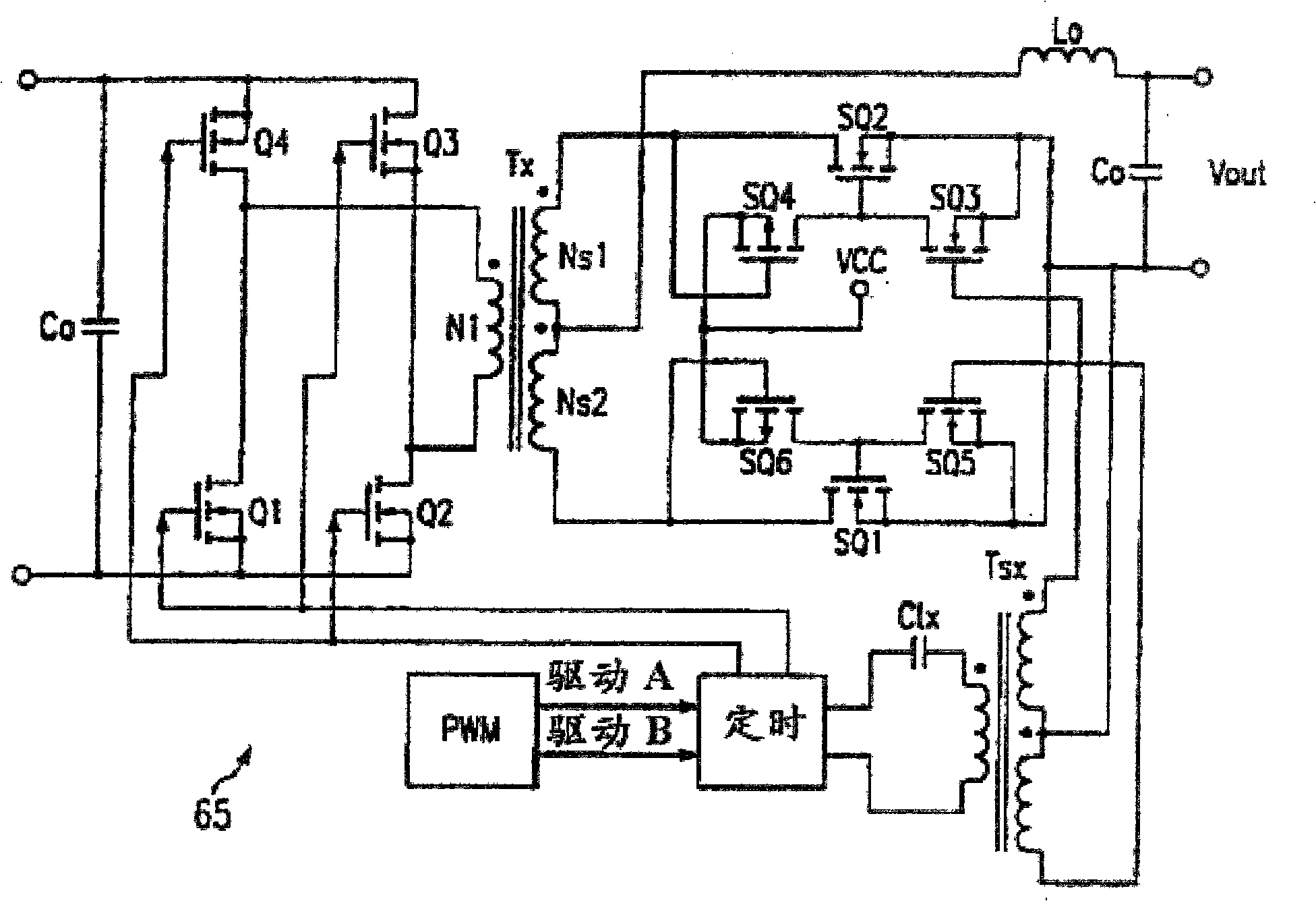
At the same time, the control gates of SQ4 and SQ6 transistors in the drive circuit are directly connected to the secondary winding of the main transformer, and the maximum limit voltage borne by the control gates of SQ4 and SQ6 transistors is only 20V, so when the output voltage of the secondary winding of the main transformer When high, the drive circuit is unusable and has great limitations

Method used


Image

  • Synchronous rectification external drive proposal
  • Synchronous rectification external drive proposal
  • Synchronous rectification external drive proposal

Examples


Embodiment Construction

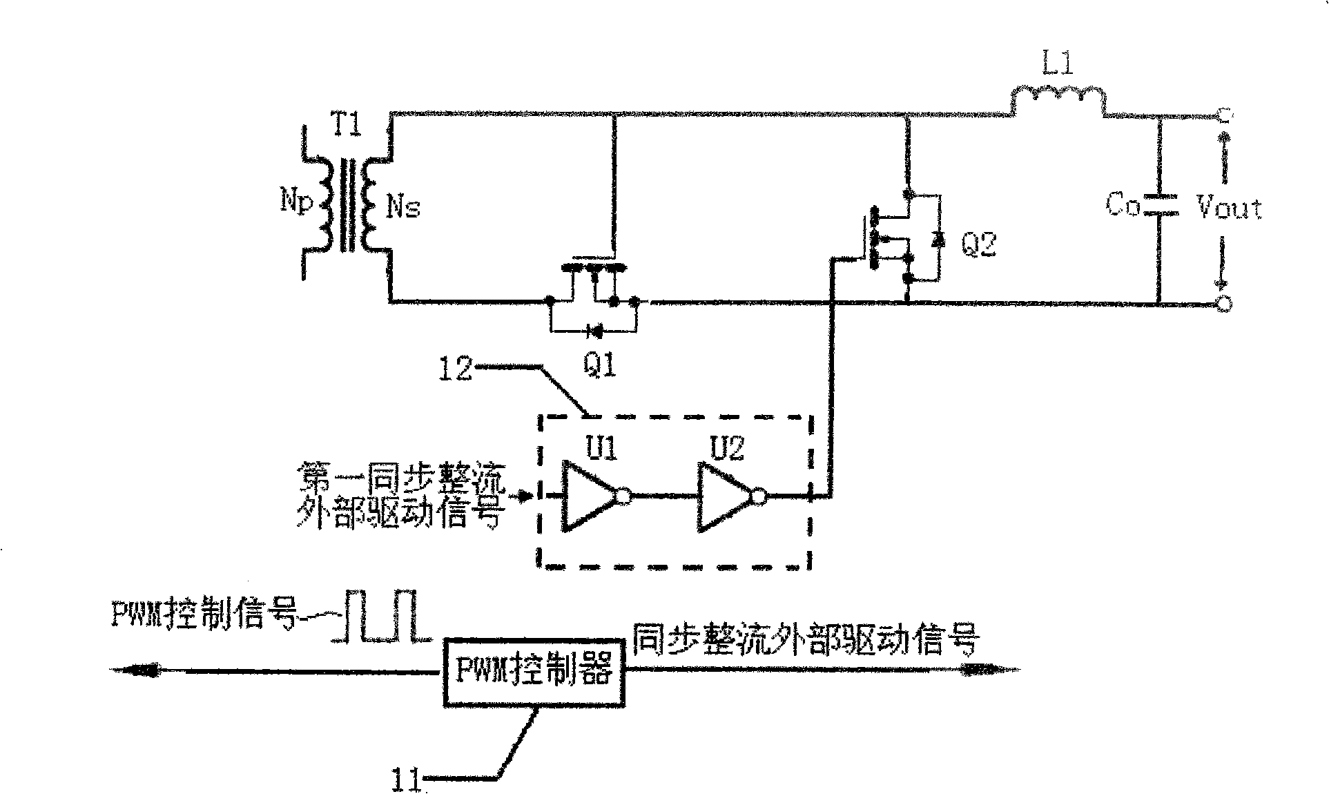
[0035] The core idea of ​​the present invention is: the input synchronous rectification external drive signal is firstly processed by the first inverting power drive unit and the second inverting power drive unit to drive the synchronous rectifier, so as to ensure the conduction and cut-off of the synchronous rectifier in normal operation, At the same time, when the power converter fails or is powered off normally, the synchronous rectification external drive signal does not exist, and its voltage remains at a low level, due to the existence of the first inverting power drive unit, the output of the first inverting power drive unit immediately maintains a high level , the high-level signal is reversed by the second inverting power drive unit, and immediately keeps the low-level output to turn off the synchronous rectifier, which ensures the stop of the synchronous rectifier when the power converter fails or is powered off normally, effectively preventing the output The voltage ...


PUM


Abstract

The invention discloses a synchronous rectification external drive circuit, which comprises a main transformer (T1) with a primary winding and a secondary winding, a first synchronous rectifier (Q1) and a second synchronous rectifier (Q2), a first output inductance and a first external drive circuit (12); wherein, the drain electrodes of the first synchronous rectifier and the second synchronous rectifier are respectively connected with the secondary winding of the main transformer; one end of the first output inductance is connected with the secondary winding of the main transformer; the first external drive circuit receives external drive signals of the first synchronous rectifier and the output thereof is connected with a grid of the second synchronous rectifier (Q2) and controls the breakover and cutoff of the second synchronous rectifier (Q2). The design proposal of the synchronous rectification external drive provided by the invention solves the problem that the synchronous rectifier of a supply converter in the prior art is not shut off timely or the shutoff time is so long to cause that the output voltage inversely irrigates and the output presents the negative pressure. The circuit is simple, has low cost, wide applicability and high effect.

Description

technical field [0001] The present invention relates to the field of power electronics, and more specifically, relates to an externally driven synchronous rectification design scheme for a power converter. Background technique [0002] Products in communication, communication and other fields widely use isolated power supplies. With the development of technology, the output voltage of isolated power supplies is required to be lower and lower, the output current is larger and the efficiency is higher and higher. Therefore, the traditional Diode rectification has been replaced by MOSFET synchronous rectification, which can output lower voltage, higher current, and provide higher efficiency. At present, synchronous rectification has been widely used in the rectification technology of isolated power converters, and many chip manufacturers have launched PWM controllers with external drive signals for synchronous rectification. [0003] In the isolated power converter rectificati...

Claims


Application Information

Patent Timeline
IPC IPC(8): H02M7/537
Inventor 李成勇
Owner 李成勇
Learn More