Check patentability & draft patents in minutes with Patsnap Eureka AI!

A commutating auto zero amplifier

An automatic zeroing and amplifier technology, applied in amplifiers, differential amplifiers, DC-coupled DC amplifiers, etc., can solve problems such as noise performance limitations and poor noise performance, and achieve the effect of minimizing limitations

Inactive Publication Date: 2009-09-09
NXP BV
View PDF0 Cites 6 Cited by
  • Summary
  • Abstract
  • Description
  • Claims
  • Application Information

AI Technical Summary

Problems solved by technology

But such amplifiers have poor noise performance
The single-stage stability of this system is ideal for current measurement functions, but its noise performance is a limitation

Method used


Image

  • A commutating auto zero amplifier
  • A commutating auto zero amplifier
  • A commutating auto zero amplifier

Examples


Embodiment Construction

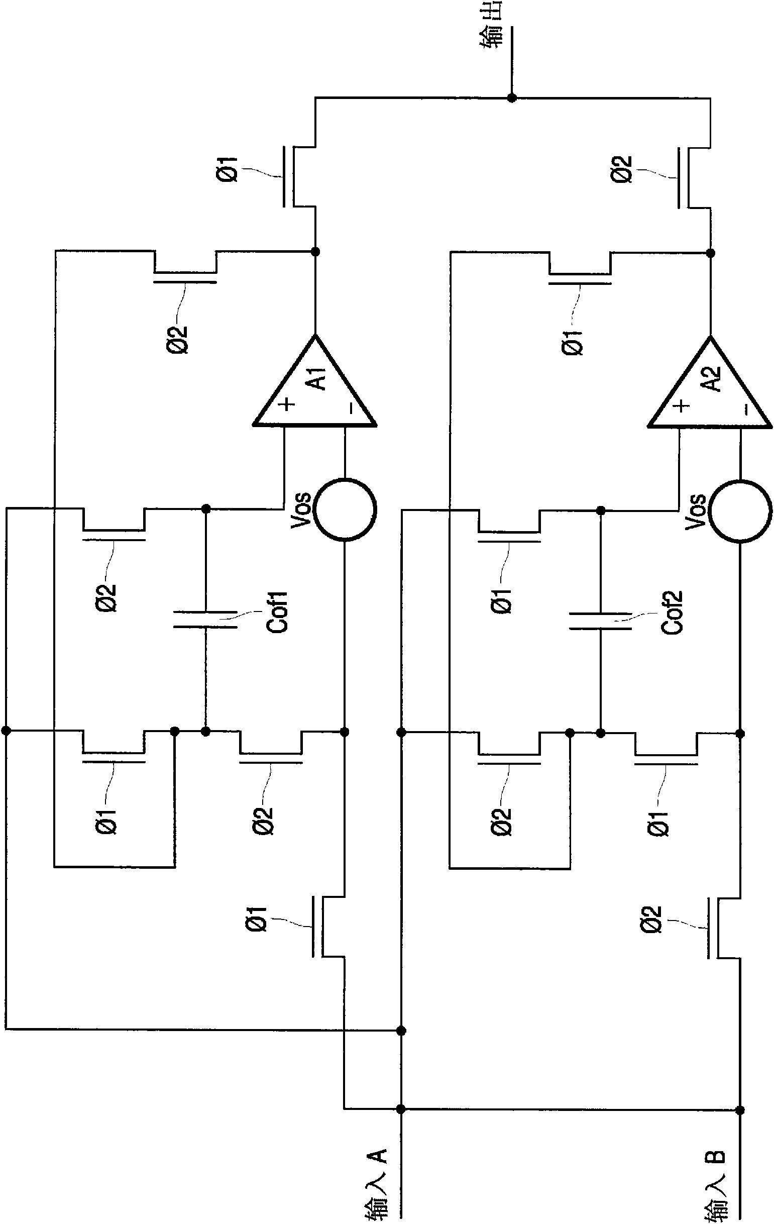
[0034] figure 1 A known alternating auto-zero amplifier is shown.

[0035] The circuit includes two amplifiers, A1 and A2, each of which can be independently routed to the output by an output switch. Each amplifier has capacitors Cof1 and Cof2 for storing an offset voltage to be applied to the non-inverting terminal of the amplifier. Two inputs, A and B, define the non-inverting (positive) and inverting (negative) main inputs.

[0036] Operation proceeds in two main states, in each state the respective CMOS switches are turned on and off. As shown, there are two control signals for the gate of the CMOS transistor with

[0037] In this way, the circuit switches between two modes in which one op amp is connected to the output (called "output mode" or "closed-loop mode") and the other op amp is in offset correction mode (called "null mode"). ").

[0038] When in closed loop output mode ( control A1, Control A2), one input is coupled to the inverting input, and the o...


PUM


Abstract

A commutating auto zero amplifier system, comprises a first amplifier (A1 ), a second amplifier (A2) and a switching arrangement which defines a two phase operation, with one amplifier in an output mode providing the output and the other amplifier in a zeroing mode during each phase. A capacitor arrangement (Cof1. Cot1 ) stores offset voltages, a buffer amplifier (B) couples the output from the amplifier in the output mode to an input of the amplifier in the zeroing mode. This eliminates voltage swings at the output of an amplifier as it switches between modes of operation.

Description

technical field [0001] This invention relates generally to electronic amplifiers, and more particularly to alternating auto-zero amplifiers. Background technique [0002] There are many applications that require a low offset amplifier, such as use as part of a current sensing circuit. [0003] A typical target specification for this type of amplifier is a low system offset voltage, such as less than 1 μV. Integrated circuit amplifiers are typically formed using CMOS technology and are less skewed than would be achieved by matching CMOS devices based on the fabrication circuit process. [0004] Indeed, one of the biggest difficulties in designing a precision CMOS op amp is reducing errors caused by mismatches in MOS transistors. There are various methods that can be used to minimize error, each with its own advantages, but all have their limitations. There are three main types of existing systems: [0005] 1 chopper amplifier [0006] Such systems offer very low noise a...

Claims


Application Information

Patent Timeline
IPC IPC(8): H03F3/45
CPCH03F2203/45682H03F3/45475H03F2203/45726H03F2203/45138H03F2200/261H03F2203/45551
Inventor 安德鲁·斯蒂尔
Owner NXP BV
Features
  • R&D
  • Intellectual Property
  • Life Sciences
  • Materials
  • Tech Scout
  • Unparalleled Data Quality
  • Higher Quality Content
  • 60% Fewer Hallucinations
Learn More