
Roll feeder

A technology of feeder and roller type, which is applied in the field of roller feeder, can solve problems such as troublesome replacement operations, and achieve the effect of simplified structure

Inactive Publication Date: 2014-04-09
欧立机电株式会社
View PDF9 Cites 0 Cited by
  • Summary
  • Abstract
  • Description
  • Claims
  • Application Information

AI Technical Summary

Problems solved by technology

For this reason, the replacement work of the roll is troublesome

Method used


Image

  • Roll feeder
  • Roll feeder
  • Roll feeder

Examples


Embodiment Construction

[0041] Hereinafter, preferred embodiments of the present invention will be explained in detail with reference to the accompanying drawings.

[0042] A. The overall structure of the roller feeder

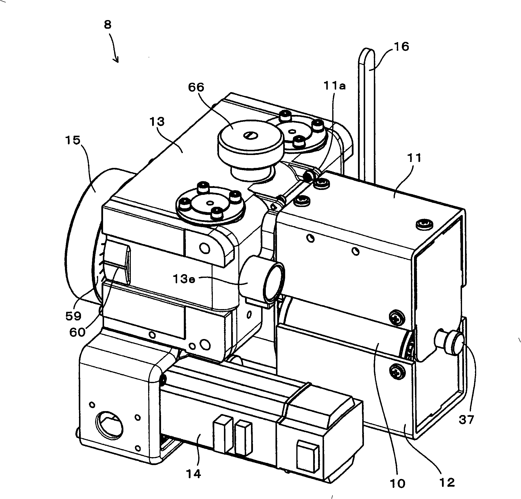
[0043] figure 1 is a perspective view showing the roller feeder 8 of the embodiment, with the covers 11 , 12 in the closed position (state where the covers 11 , 12 are in the closed position to be described).

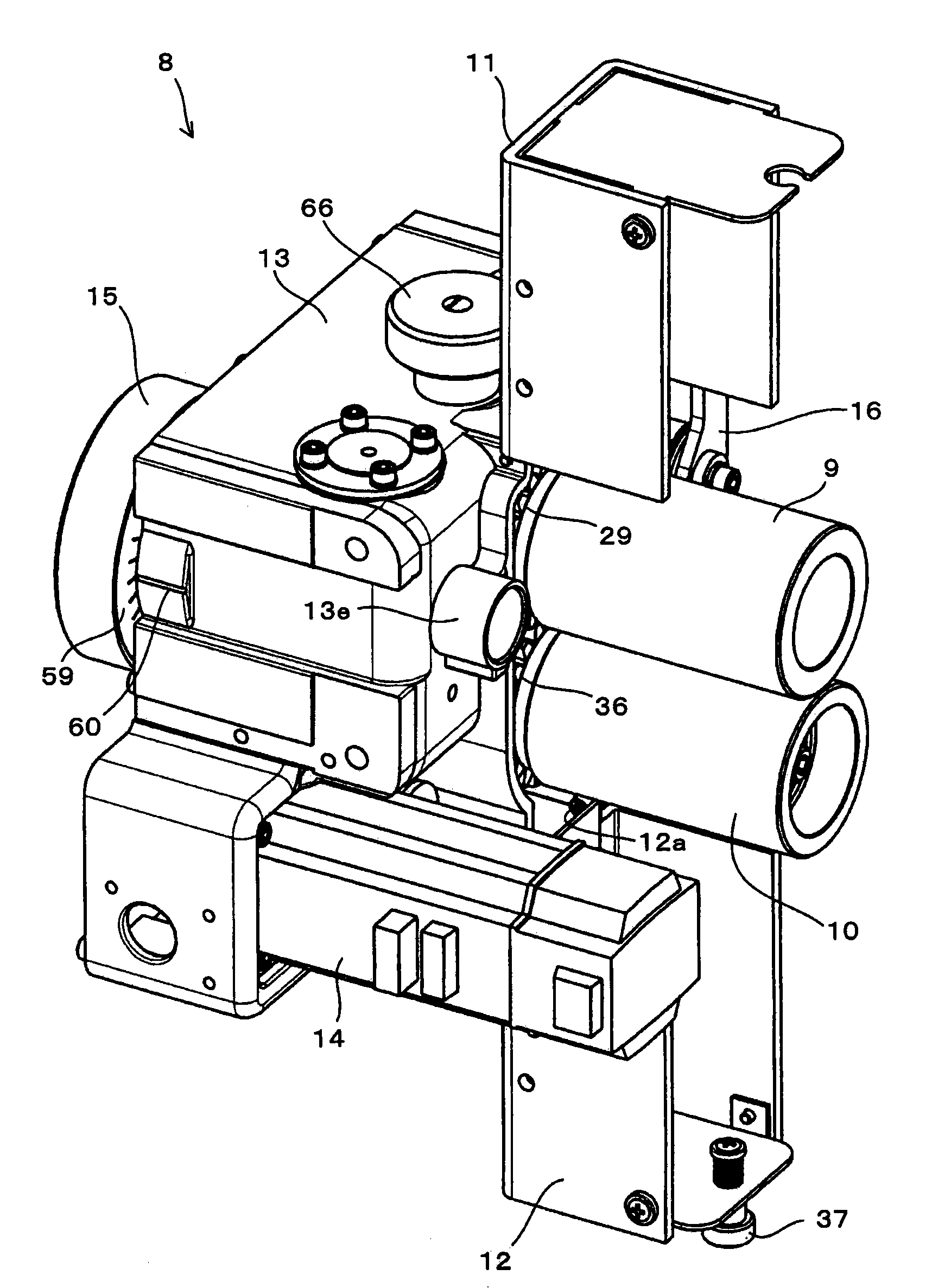
[0044] figure 2 is a perspective view showing the roller feeder 8 with the covers 11, 12 in the open position (the state where the covers 11, 12 are in the open position to be described).

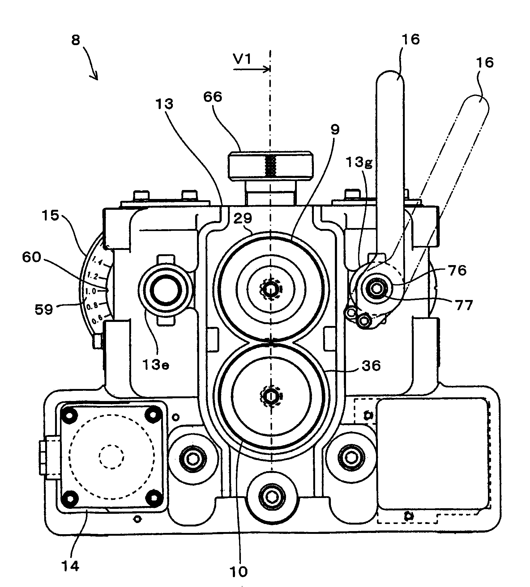
[0045] image 3 It is a front view of the roller feeder 8.

[0046] Figure 4 It is a rear view of the roller feeder 8. Figure 4 Showing that lid (lid) 17, handle 15, etc. have been removed ( Figure 7 shown in ), which will be described later.

[0047] Figure 5 It is a right side view of the roller feeder 8.

[0048] Figure 6A is a vertical section view of the roller feeder ...


PUM


Abstract

The present invention discloses a roll feeder (8) which comprises a pair of rollers (9, 10) that used to realize feeding operation of ribbon material through fastening and rotating. A supporting member (frame 13) is set on one side of each roller (9, 10) and each roller (9, 10) on each side is capable of rotating freely. Each roller is hollow inside. In a cantalever suspension structure, each roller is mounted on the supporting member and stretches into axis (18, 19) of each roller. An upper roller (9) is set as to rotate freely o circumference of a axis (18), and the axis (18) conjugates with a rolling bearing (23) between the outer annulus surface of the axis (18) and inner annulus surface of the roller (9), and can swing around central line of the roller (9) through relative movement of the rolling bearing (23) in a declining direction of central line of the axis (18).

Description

technical field [0001] The invention relates to a roll feeder which feeds strip-shaped material, for example to an extrusion machine. Background technique [0002] In general, a strip-shaped plate material composed of steel, aluminum, etc. (hereinafter referred to as a strip-shaped material) is continuously supplied to an extrusion machine with a series of equipment, and mechanical processing such as extrusion processing, cutting processing, etc. is performed, such as in Japan Patent Application Publication No. 2003-181573 is published. [0003] In the above-mentioned apparatus, extrusion processing and the like are performed (see Japanese Patent Application Laid-Open Publication Nos. 2003-181573 and 2004-142876). That is, as the strip-shaped material (ie, coil stock) wound into a roll is rotated in the unwinding direction by a mechanism called an uncoiler, a desired strip is drawn out from the outer circumference. shape material. The above strip material is fed out using...

Claims


Application Information

Patent Timeline
Patent Type & Authority Patents(China)
IPC IPC(8): B21C33/00B65H20/02
Inventor 铃木智彦武内诚治枝泽正人
Owner 欧立机电株式会社
Learn More