Large steam turbine-generator set rotor crack fault real-time diagnosis method

A technology for steam turbine generator sets and rotor cracks, which is applied in the testing of mechanical components, testing of machine/structural components, measuring devices, etc., can solve the problems of long cycle time and high economic cost of diagnosis, and achieve scientific methods and reliable conclusions

Inactive Publication Date: 2009-09-16
NORTH CHINA ELECTRIC POWER UNIV (BAODING)
View PDF0 Cites 38 Cited by
  • Summary
  • Abstract
  • Description
  • Claims
  • Application Information

AI Technical Summary

Problems solved by technology

The diagnosis of the rotor crack fault of the steam turbine generator set is completed b

Method used


Image

  • Large steam turbine-generator set rotor crack fault real-time diagnosis method
  • Large steam turbine-generator set rotor crack fault real-time diagnosis method
  • Large steam turbine-generator set rotor crack fault real-time diagnosis method

Examples


Embodiment

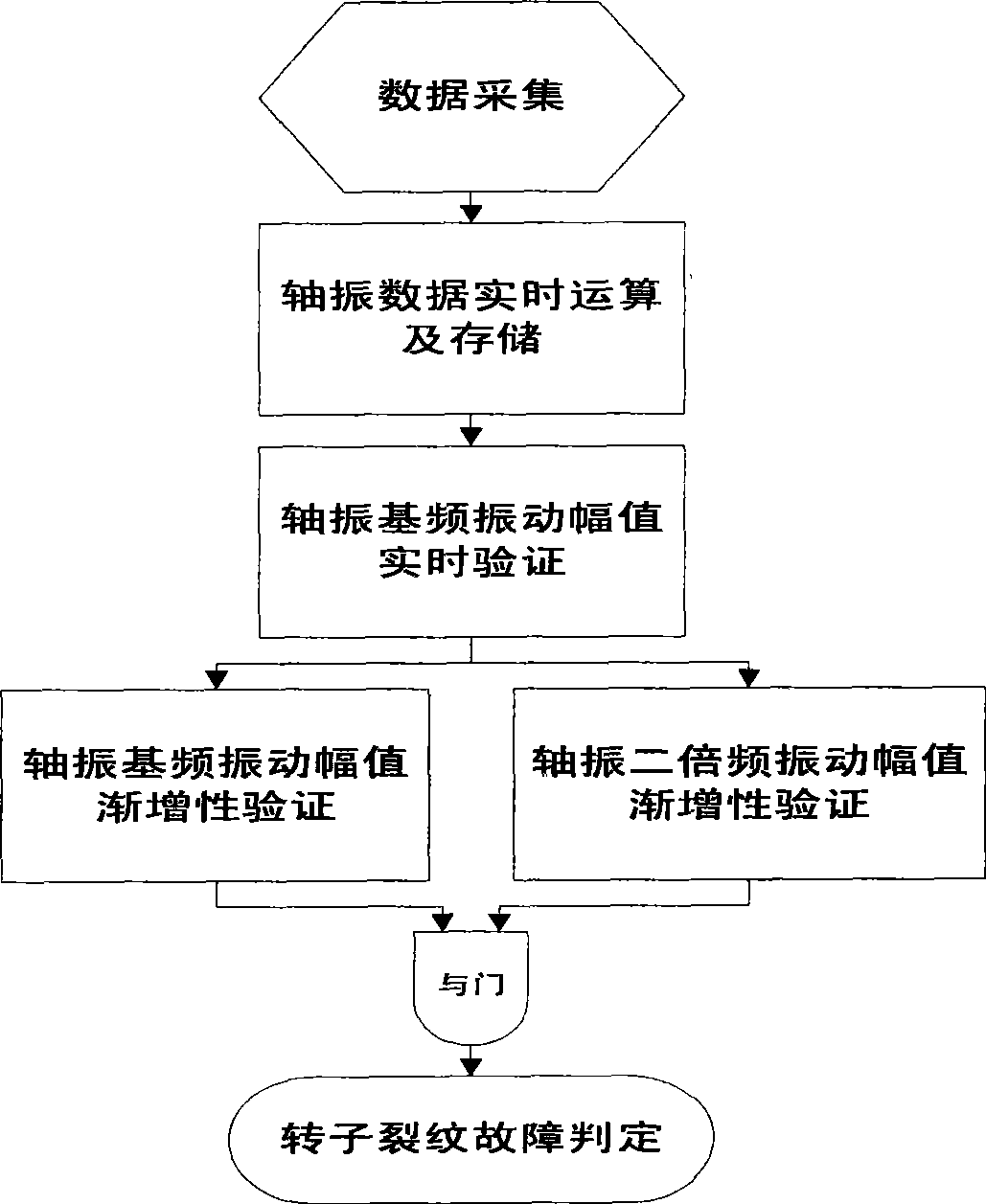
[0037] The method can be used to realize real-time monitoring, analysis and diagnosis of the rotor crack fault of the turbogenerator. The shaft vibration signal of the turbogenerator set required by the diagnosis method and the key phase signal required for the analysis and processing of the vibration signal can be obtained from the monitoring instrument (TSI) equipped with the turbogenerator set or from professional vibration data acquisition and conditioning equipment. In this embodiment, the shaft vibration signal of the steam turbine generator set and the key-phase signal required for the analysis and processing of the vibration signal are obtained from professional vibration data acquisition and conditioning equipment connected to the vibration sensor. exist Figure 4 In the schematic diagram of monitoring the crack fault of the rotor of the steam turbine generator set shown, the high-speed data acquisition card is inserted into the slot provided by the industrial microco...


PUM


Abstract

The invention discloses a large steam turbine-generator set rotor crack fault real-time diagnosis method belonging to the filed of mechanical vibration state monitoring and fault diagnosis. Necessary computational analysis and judgment for vibration data are carried out by collecting the vibration signal of a rotor shaft of a steam turbine. The shaft vibration base frequency vibration amplitude and double frequency vibration amplitude at both sides of the rotor are computed in real time and the shaft vibration base frequency vibration amplitude is validated in real time so that the shaft vibration base frequency vibration amplitude at any side of the rotor is judged whether to be larger than vibration amplitude threshold value. Combined with least square method and product-moment correlation coefficient calculating method, real-time quantitative computational analysis, such as incremental validation of the shaft vibration base frequency vibration amplitude and incremental validation of double frequency vibration amplitude of shaft vibration, is carried out on the vibration data of shaft vibration base frequency. Based on the quantitative computational analysis and combined with each verification result, on-line diagnosis of the generator set whether to have rotor crack fault is automatically carried out in real time. The method has the advantages of scientific method and reliable conclusion, and on-line monitoring and fault diagnosis can be automatically realized in real time.

Description

technical field [0001] The invention belongs to the field of vibration state monitoring and fault diagnosis of rotating machinery, and in particular relates to a real-time diagnosis method for rotor crack faults of a large-scale turbo-generator set for real-time on-line automatic monitoring of the vibration state of a large-scale turbo-generator set. Background technique [0002] Once the rotor of the turbogenerator has a crack failure, the potential threat to the equipment is huge, and it may lead to a catastrophic accident of shafting fracture. Most of the rotor cracks are caused by fatigue damage. Due to stress corrosion in the old units with a long operating time, microcracks will be generated at the position of the original induction point of the rotor, and then with the continuous effect of environmental factors, the microcracks will gradually expand and develop into macrocracks. Crack initiation points are usually places where the stress is high and the material is d...

Claims


Application Information

Patent Timeline
IPC IPC(8): G01M13/00
Inventor 宋光雄
Owner NORTH CHINA ELECTRIC POWER UNIV (BAODING)
Why Eureka
Try Eureka