Structural element of an aircraft

A technology for aircraft and engine nacelles, which is applied to aircraft parts, aircraft power plant components, engine components, etc., and can solve the problems of complex and unsatisfactory manufacturing process of structural parts

Inactive Publication Date: 2009-09-16
AIRBUS OPERATIONS (SAS)
View PDF0 Cites 2 Cited by
  • Summary
  • Abstract
  • Description
  • Claims
  • Application Information

AI Technical Summary

Problems solved by technology

[0015] From this point of view, the effect of using composite materials according to the prior art is not satisfactory, because the practice of adding thermal insulation materials, such as adding fire shielding layers, will complicate the process of making structural parts, so the use of composite materials The resulting weight savings are completely outweighed by the use of the fire shielding treatment

Method used


Image

  • Structural element of an aircraft
  • Structural element of an aircraft
  • Structural element of an aircraft

Examples


Embodiment Construction

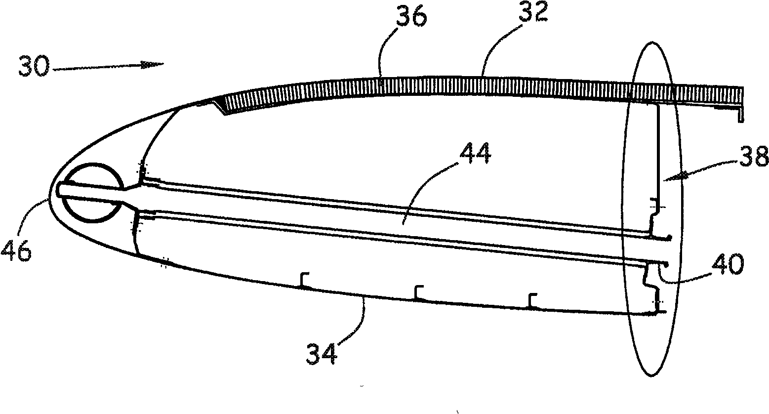
[0024] exist image 3 In , the numeral 30 represents an air inlet of the aircraft engine nacelle. The air inlet has an inner surface 32 capable of contacting the motive air flow flowing inside the nacelle and an outer surface 34 capable of contacting the motive air flow flowing outside the nacelle.

[0025] The inner surface 32 may have a sound-insulating shield or surface 36. The inner and outer surfaces will not be described in detail because those in the art are well-known.

[0026] The intake duct 30 includes a structural member called the rear bracket 38, which connects the inner surface 32 and the outer surface 34 and bears various forces acting on the structural member, such as bending stress acting on the intake duct, Rotational forces or other forces, such as the weight of the inlet, and various forces generated by turbulence.

[0027] This rear bracket 38 may include an opening to provide a mounting guide 40 for securing the piping 44 intended for the anti-icing sy...


PUM


Abstract

The invention concerns a rear frame of an air intake of a nacelle of an aircraft, characterized in that it is partly made of fiber-reinforced geopolymer resin-based composite material and comprises at least one part (56) that surrounds an opening provided for the passage of a de-icing system made of fiber-reinforced geopolymer-resin based composite material and at least one other part (58) made of metal.

Description

technical field [0001] The invention relates to a structural part on an aircraft that may withstand high temperatures, especially the rear bracket of the aircraft engine nacelle. Background technique [0002] The aircraft includes some structural parts, and their function is mainly to ensure the acquisition of force or the transmission of force between various parts on the above-mentioned structural parts. These structural parts mainly include the external supports of the aircraft that can be in contact with the air and give the structural parts a certain rigidity. [0003] figure 1 Shown is a structural element provided on the air intake 10 of the aircraft, which is placed at the front of the nacelle in which the motor unit is built. This structural member, referred to as the rear bracket 12 , connects the inner surface 14 of the nacelle to the outer surface 16 of the nacelle. The rear bracket 10 is responsible for bearing various forces acting on the air intake, such as...

Claims


Application Information

Patent Timeline
IPC IPC(8): B64C1/40B64D15/04B64D29/00C04B12/00
CPCF02C7/04C04B20/0048F05D2300/603F05C2253/16C04B2111/00982B64D33/02Y02T50/672F05C2253/04F05C2253/20F05D2300/44B64D2033/0233F05D2300/614B64D2033/0206C04B28/006F02C7/047B64D15/04Y02P40/10Y02T50/60C04B14/386C04B20/02C04B14/42C04B14/46C04B16/0691
Inventor 阿兰·波特布律诺·梅达
Owner AIRBUS OPERATIONS (SAS)
Why Eureka
Try Eureka