

Retainer of ball bearing
A cage and ball bearing technology, applied in the field of rolling bearings, can solve problems such as shortening and grease leakage bearing life, and achieve the effect of extending operating life and prolonging residual time.
- Summary
- Abstract
- Description
- Claims
- Application Information
AI Technical Summary
Problems solved by technology
Method used
Image

Examples
Embodiment 1
[0028] Embodiment 1 of the present invention passes through Figure 1 to Figure 3 Be explained.
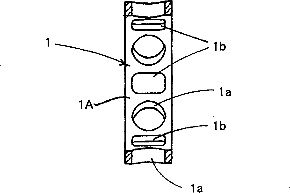
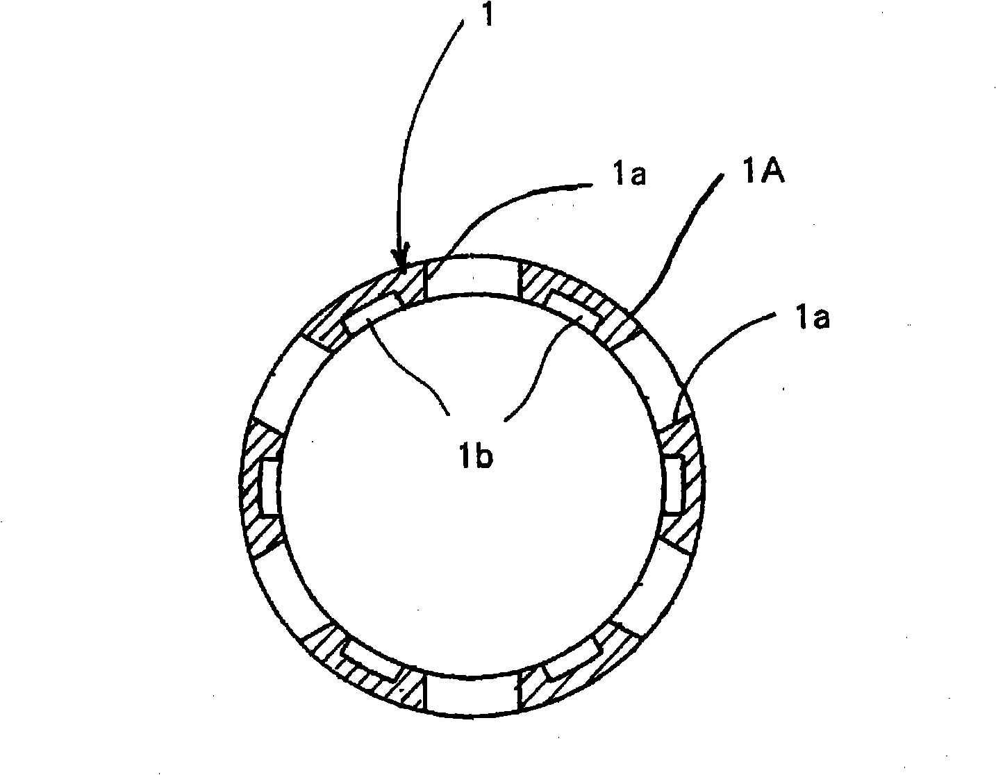
[0029] figure 1 It is a longitudinal sectional view of the cage 1 of the present embodiment, figure 2 is a transverse cross-sectional view of the cage 1.
[0030] The cage 1 is formed of an annular main portion 1A made of a composite material such as cloth phenolic resin and formed so as to be permeable to grease base oil.
[0031] 1a is a circular concave hole for holding a ball, the concave hole 1a penetrates the main part 1A in the radial direction, and the inner periphery is formed in a cylindrical shape.
[0032] 1b is a substantially square recess, and the recess 1b is recessed in the middle part of each adjacent recessed hole 1a, 1a in the inner peripheral surface of the said main part 1A.
[0033] In addition, the depth of the recess 1b is set not to affect the strength of the main portion 1A, for example, about half the thickness of the main portion 1A.
[0034] Nex...
Embodiment 2
[0042] Embodiment 2 of the present invention passes through Figure 4 Be explained.
[0043] Figure 4 It is a longitudinal sectional view of the cage 7 of this embodiment.
[0044] The cage 7 is formed of an annular main portion 7A made of a composite material such as cloth phenolic resin and formed in a widened form.
[0045] A plurality of cylindrical concave holes 7 a for holding balls penetrate the main portion 7A in the radial direction.
[0046] 7b is a recess, and the recess 7b is formed in a convex shape having a thin protrusion 7bt on one side of a substantially square shape, and each recess 7b is at the center of the recessed hole 7a connecting the inner peripheral surface of the main part 7A. Both sides of the central line of the part are arranged symmetrically so that each protruding part 7bt faces the central line. In addition, the depth of the recess 7b is about half of the thickness of the main part 7A, for example.
[0047] In addition, the pair of right ...
Embodiment 3
[0053] Embodiment 3 of the present invention passes through Figure 5 and Figure 6 Be explained.
[0054] Figure 5 It is a longitudinal sectional view of the cage 11 of this embodiment, Figure 6 is a transverse cross-sectional view of the cage 11.
[0055] In the annular main portion 11A of the cage 11 of the present embodiment, the inner peripheral surface of the concave hole 11 a for holding the ball is a spherical concave surface corresponding to the ball.
[0056] Here, the holder 11 is formed in a form divided into two parts, and 11c is a joint portion thereof.
[0057] The recess 11b has the same shape as that of the recess 1b of the first embodiment described above.
[0058] By making the concave holes 11a holding the balls spherical in this way, it is possible to prevent the cage 11 from vibrating in the radial direction.
[0059] This retainer 11 is used in the same manner as the retainer 1 of Embodiment 1 or Embodiment 2 described above.
[0060] In addition,...
PUM
 Abstract
Description
Claims
Application Information