Hot cathode fluorescent lamp

A fluorescent lamp and hot cathode technology, applied in discharge lamps, gas discharge lamps, electrical components, etc., can solve the problems of shortened lamp life, rapid loss of electron emission materials, short circuit, etc. Effect

Inactive Publication Date: 2009-09-16
PANASONIC CORP
View PDF1 Cites 2 Cited by
  • Summary
  • Abstract
  • Description
  • Claims
  • Application Information

AI Technical Summary

Problems solved by technology

[0006] However, in the above-mentioned conventional hot cathode fluorescent lamp, there may be a danger of a short circuit between the winding portion of the filament coil and the metal sleeve covering the winding portion.
Once the short circuit occurs, the lamp starts to light up without sufficient preheating of the filament coil. Compared with the case of starting to light up under the fully preheated state, the electron emission material is sputtered too much, and the loss of the electron emission material Too fast, so there is a problem of shortening the life of the lamp

Method used


Image

  • Hot cathode fluorescent lamp
  • Hot cathode fluorescent lamp
  • Hot cathode fluorescent lamp

Examples


Deformed example 1

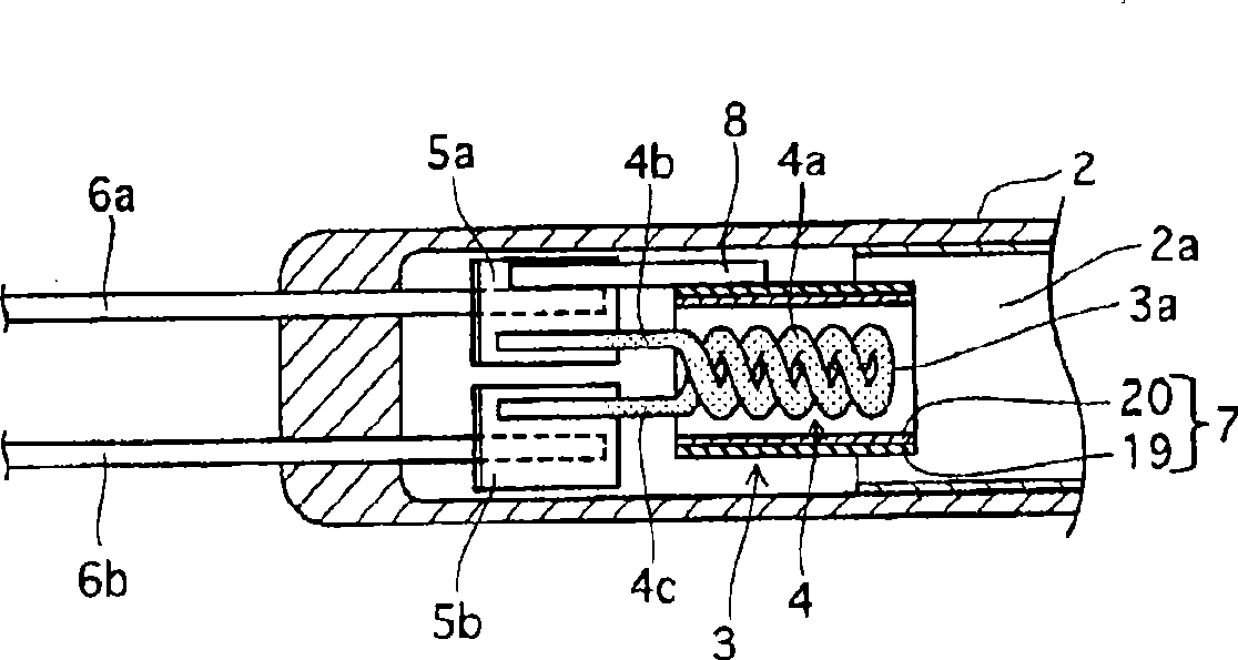
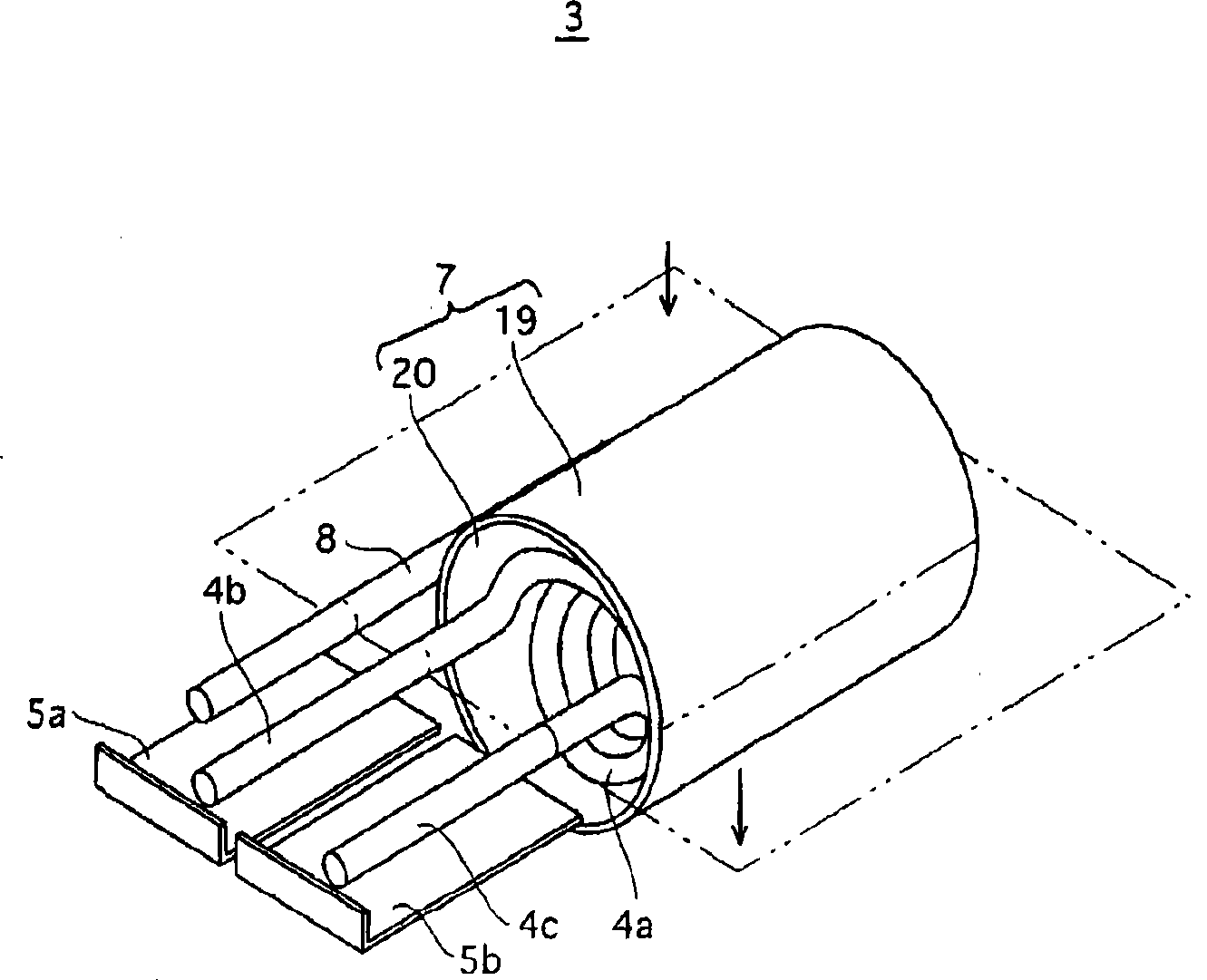
[0065] As shown in FIG. 3( b ), the insulating film 21 of Modification 1 is thicker on the side of the first lead portion 4 b and the second lead portion 4 c than on the side of the folded end of the winding portion 4 a.

[0066] For example, in the insulating film 21, the thickness t2 of the opening end of the substrate 19 on the side of the folded end is set to 0.05 mm, and the thickness t3 of the opening end of the substrate 19 on the side of the lead parts 4b and 4c is set to 0.15 mm.

[0067] The thickness of the insulating film 21 can be adjusted as follows, that is, in the case of using a glaze or a slurry-like material, the glaze or the slurry-like material is coated on the entire surface of the inner peripheral surface of the base body 19, and in the firing process In this process, the base body 19 is rotated around its axis, and the axis of the base body 19 is maintained at a right angle with respect to the vertically downward direction, and then gradually becomes an ...

Deformed example 2

[0070] As shown in FIG. 3( c ), in the insulating film 22 of Modification 2, the thickness of the side farther from the sleeve lead 8 becomes smaller than that of the insulating film 21 closer to the sleeve 7 in the axial direction of the sleeve 7 compared to the insulating film 21 of Modification 1. The thickness of one side of the extended sleeve lead 8 is large.

[0071] For example, in the insulating film 22, on the side close to the sleeve lead 8, the thickness t4 of the opening end of the substrate 19 on the side of the turned-back end of the winding portion 4a is set to 0.05 mm, and the thickness t4 of the substrate 19 on the side of the lead wire portions 4b and 4c is set to 0.05 mm. The thickness t5 of the opening end of the coil is set to 0.10mm, and on the side away from the sleeve lead wire 8, the thickness t6 of the opening end of the substrate 19 on the side of the folded end of the winding part 4a is set to 0.10mm, and the lead wire parts 4b, 4c- The thickness t...


PUM


Abstract

A filament coil (4) has a winding portion (4a) to which electron emitting material adheres. When the filament coil (4) is covered by a heat-resistant sleeve (7), if a shortcircuit occurs between the winding portion of the filament coil and the sleeve inner circumferential surface for the hot cathode fluorescent lamp arranged at each end of the glass bulb upon lightening and the lamp starts lightening before the winding portion is sufficiently preheated, the electron emitting material is excessively sputtered and worn out, which reduces the lamp service life. This can be prevented by using such a configuration that at least a part of the inner circumferential surface of the sleeve is not conductive.

Description

technical field [0001] The present invention relates to a hot cathode fluorescent lamp mainly used as a backlight of a liquid crystal display device. Background technique [0002] In recent years, liquid crystal display devices have also been required to increase in size, such as liquid crystal television receivers, and in response to this increase in size, there has also been a need to increase the size of low-pressure discharge lamps for backlights. [0003] In response to the need for larger size, the inventors have studied the use of hot cathode fluorescent lamps for backlights because they have higher luminous efficiency than cold cathode fluorescent lamps, a large amount of light emitted per lamp, and easy assembly. [0004] In a hot cathode fluorescent lamp, a filament coil coated with an electron emission material is generally used, but the electron emission material is sputtered during lighting, and there is a problem that its life is shorter than that of a cold cat...

Claims


Application Information

Patent Timeline
Patent Type & Authority Applications(China)
IPC IPC(8): H01J61/067
CPCH01J61/0672
Inventor 大竹史郎重田照明荒川刚清水伸浩
Owner PANASONIC CORP
Why Eureka
Try Eureka