Supercharge Your Innovation With Domain-Expert AI Agents!

Plasma display device

A display device, plasma technology, applied to static indicators, televisions, instruments, etc., can solve problems such as power loss

Inactive Publication Date: 2009-09-23
HITACHI LTD
View PDF1 Cites 0 Cited by
  • Summary
  • Abstract
  • Description
  • Claims
  • Application Information

AI Technical Summary

Problems solved by technology

On the other hand, by providing the bidirectional switch 20, power loss (power loss) occurs when a sustain pulse is applied during the sustain period.

Method used


Image

  • Plasma display device
  • Plasma display device
  • Plasma display device

Examples


Embodiment Construction

[0016] Embodiments of the present invention will be described in detail below using the drawings.

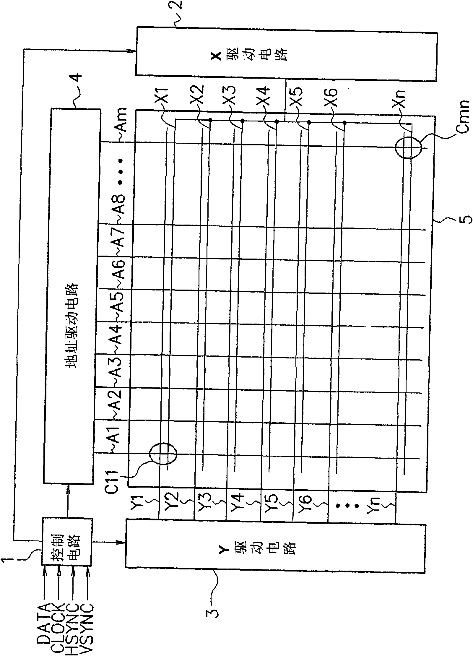
[0017] figure 1 It is a diagram showing a configuration example of a plasma display device in an embodiment of the present invention.

[0018] The control circuit 1 receives image data DATA, a clock signal CLOCK, a horizontal synchronization signal HSYNC, and a vertical synchronization signal VSYNC, and controls the X driving circuit 2 , the Y driving circuit 3 and the address driving circuit 4 .

[0019] The X drive circuit 2 is constituted by a circuit that repeatedly performs sustain discharge, and supplies a predetermined voltage to a plurality of X electrodes (sustain electrodes) X1, X2, . . . . Hereinafter, each of the X electrodes X1, X2, .

[0020] The Y drive circuit 3 is composed of a circuit for sequentially scanning lines to select a row to be displayed, and a circuit for repeatedly performing sustain discharge, and supplies a predetermined voltage to a plurality ...


PUM


Abstract

The invention relates to a plasma display device, which comprises a capacitance C1 connected between a high potential side terminal of a scan driver and a low potential side terminal thereof for applying a predetermined potential to a Y electrode; a switch SWY5 clamping a second potential line LN2 connected to the low potential side terminal to a potential Vs and a switch SWY6 clamping the second potential line LN2 to a ground potential; and a switch SWY7 provided that is capable of cutting off a connection between the second potential line LN2 and the ground potential via the switch SWY6. When the second potential line LN2 is a negative potential, it is possible to cut off the connection to the ground potential by turning the switch SWY7 off. This prevents a current from flowing via a parasitic diode of the switch SWY6. Thereby, a plasma display device capable of reducing the number of elements constituting a drive circuit, and decreasing power loss is provided.

Description

technical field [0001] The present invention relates to plasma display devices. Background technique [0002] In the driving of a plasma display panel (PDP), one field is composed of a plurality of subfields, and gray scale display is realized by selecting which subfield to turn on a cell. Moreover, each subfield is composed of the following periods: a reset period for initializing the state of wall charges on the electrodes; an address period for selecting cells based on display data and adjusting the state of wall charges to light up the cells; Sustain period in which data cells are turned on (selected cells are discharged to emit light corresponding to display data). [0003] Image 6 It is a circuit diagram showing a Y drive circuit for driving Y electrodes (scanning electrodes) in a conventional plasma display device. The Y drive circuit applies a predetermined voltage to the plurality of Y electrodes. [0004] The Y drive circuit has switches SW11 to SW19, resistors...

Claims


Application Information

Patent Timeline
IPC IPC(8): G09G3/28G09G3/291G09G3/20G09G3/288G09G3/292G09G3/293G09G3/294G09G3/296G09G3/298H04N5/66
CPCG09G3/296G09G3/293G09G3/291
Inventor 山崎将史藤崎隆金泽义一
Owner HITACHI LTD
Features
  • R&D
  • Intellectual Property
  • Life Sciences
  • Materials
  • Tech Scout
  • Unparalleled Data Quality
  • Higher Quality Content
  • 60% Fewer Hallucinations
Learn More