Tube busbar joint

A technology for managing busbars and busbars, applied in the direction of connecting contact materials, clamping/spring connections, etc., can solve the problems of excessive conductor overcurrent, high cost of conversion hardware, uneven current distribution, etc., to achieve large current-carrying capacity and saving Non-ferrous metals, energy saving effect

Active Publication Date: 2009-09-23
广东日昭电工有限公司
View PDF1 Cites 3 Cited by
  • Summary
  • Abstract
  • Description
  • Claims
  • Application Information

AI Technical Summary

Problems solved by technology

[0003] The existing conductive pipe busbar joint (patent number: 01215457.1) has the following disadvantages in the actual installation process: since the end of the conductive pipe busbar is round, it is necessary to install conversion fittings during the connection with the equipment terminal, from the round surface to the Plane, connected to other equipment terminals through rectangular conductors
1. The connection between the pipe busbar and the equipment terminal needs to be equipped with conversion fittings, which is costly, wastes materials and consumes energy
2. The original joint has only two conductive planes, the cross-sectional area is small, and the conductors are split. When the current is transmitted, there will be uneven current distribution. One of the conductive plane conductors has a small overcurrent, and the other conductive plane conductor has overcurrent If it is too large, the side with high overcurrent will generate high temperature
3. The connection between the end of the pipe busbar and the conversion fitting will generate contact resistance. Due to the existence of contact resistance, in the case of high current transmission, the end of the pipe busbar and the conversion fitting will generate excessive heat. The greater the heat, the higher the resistance , the more serious the heat is, the higher the temperature will cause the pipe busbar to be blown, short circuit between phases, short circuit to ground or cause a fire and cause a greater accident

Method used


Image

  • Tube busbar joint
  • Tube busbar joint
  • Tube busbar joint

Examples


Embodiment Construction

[0021] The specific embodiments of the present invention will be further described below in conjunction with the accompanying drawings.

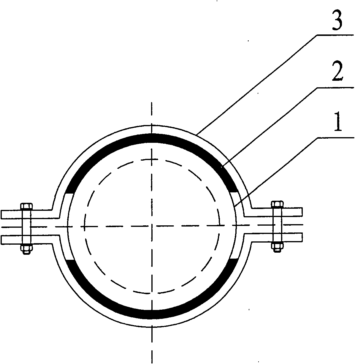
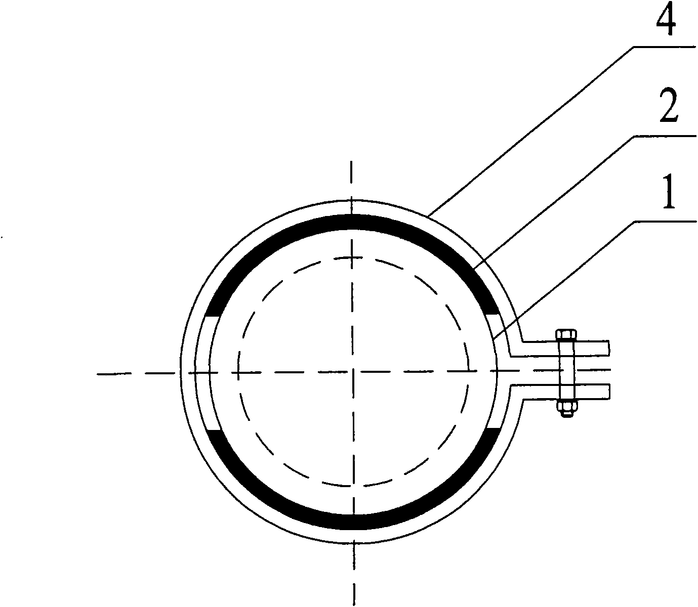
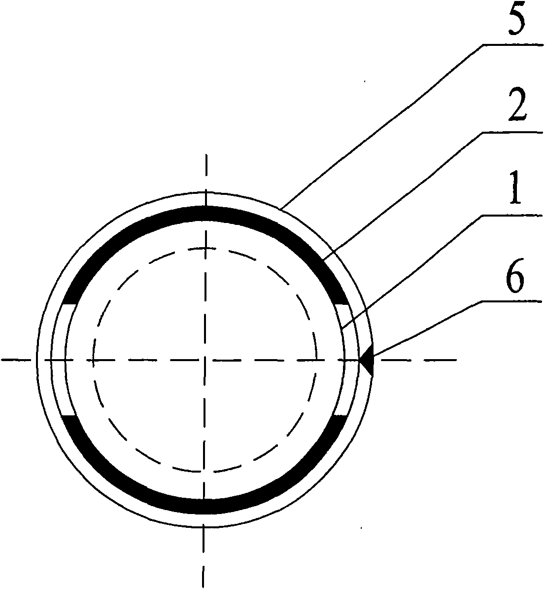
[0022] Such as figure 1 , figure 2 , Figure 5 , Figure 6 As shown, the pipe busbar joint of the present invention is that the ends of the copper and aluminum pipe busbars and copper composite pipe busbars (composite steel pipes or aluminum pipes in copper pipes) with a diameter of Φ30 mm to 500 mm and a wall thickness of 1 mm to 30 mm are hooped with openings on both sides. Or unilateral opening hoop (stainless steel, wall thickness 1mm ~ 10mm) to directly fasten soft copper and aluminum strips (according to the requirements of carrying capacity, choose one or more pieces of soft copper and aluminum strips, thickness 1mm ~ 30mm) to the busbar On the outer circle of the end (in order to strengthen the mechanical strength and carrying capacity of the end, the load area of ​​the end of the busbar can be increased, and the outer circle of ...


PUM

PropertyMeasurementUnit
diameteraaaaaaaaaa
thicknessaaaaaaaaaa
thicknessaaaaaaaaaa

Abstract

The invention discloses a tube busbar joint which is formed by adopting an anchor ear and a metallic sheath at the ends of copper and aluminium tube busbars and a copper composite tube busbar, or using an arc-shaped metallic pressing board to tightly fix soft copper and aluminium tapes on the end of the busbar by a screw bolt directly. The soft copper and aluminium tapes of the tube busbar joint is connected with terminals of other equipment, and the tube busbar joint tightly fixes the soft copper and aluminium tapes on the end of the busbar directly to form an integrated type, thus having no link bit, no contact resistance, reducing heat productivity, having large current carrying capacity, guaranteeing that the end of the busbar does not generate high temperature, and ensuring safe operation; and the busbar joint is the integrated type, thus cancelling original conversion hardware fittings, lowering cost directly, reducing the weight of the busbar and consumptive materials, and saving nonferrous metal and energy.

Description

[0001] The application in this case is a divisional application. The application date of the original application is April 24, 2007, the application number is 200710101495.7, and the name of the invention is pipe bus joint. technical field [0002] The tube busbar joint of the invention is especially suitable for connecting the end of the conductive tube busbar for transporting power frequency and large current to equipment terminals. Large current carrying capacity, low temperature rise, high mechanical strength, and improved operating safety factor. Background technique [0003] The existing conductive pipe busbar joint (patent number: 01215457.1) has the following disadvantages in the actual installation process: since the end of the conductive pipe busbar is round, it is necessary to install conversion fittings during the connection with the equipment terminal, from the round surface to the Plane, connected to other equipment terminals through rectangular conductors. 1....

Claims


Application Information

Patent Timeline
Patent Type & Authority Applications(China)
IPC IPC(8): H01R4/28H01R4/60H01R4/46
Inventor 罗志昭
Owner 广东日昭电工有限公司
Why Eureka
Try Eureka