
Plasma processing apparatus

A processing device, plasma technology, applied in the directions of plasma, gaseous chemical plating, coating, etc., can solve the problem of satisfactory plasma uniformity, achieve high uniformity, reduce the influence of end effect, and ensure axial symmetry sexual effect

Active Publication Date: 2009-09-23
SAMCO INC
View PDF2 Cites 17 Cited by
  • Summary
  • Abstract
  • Description
  • Claims
  • Application Information

AI Technical Summary

Problems solved by technology

However, including the induction coils disclosed in Patent Document 1 and Patent Document 2, in the induction coils of the plasma processing apparatus disclosed so far, it cannot be said that the uniformity of the plasma is satisfactory, and there is still room for improvement.

Method used


Image

  • Plasma processing apparatus
  • Plasma processing apparatus
  • Plasma processing apparatus

Examples


Embodiment

[0042]

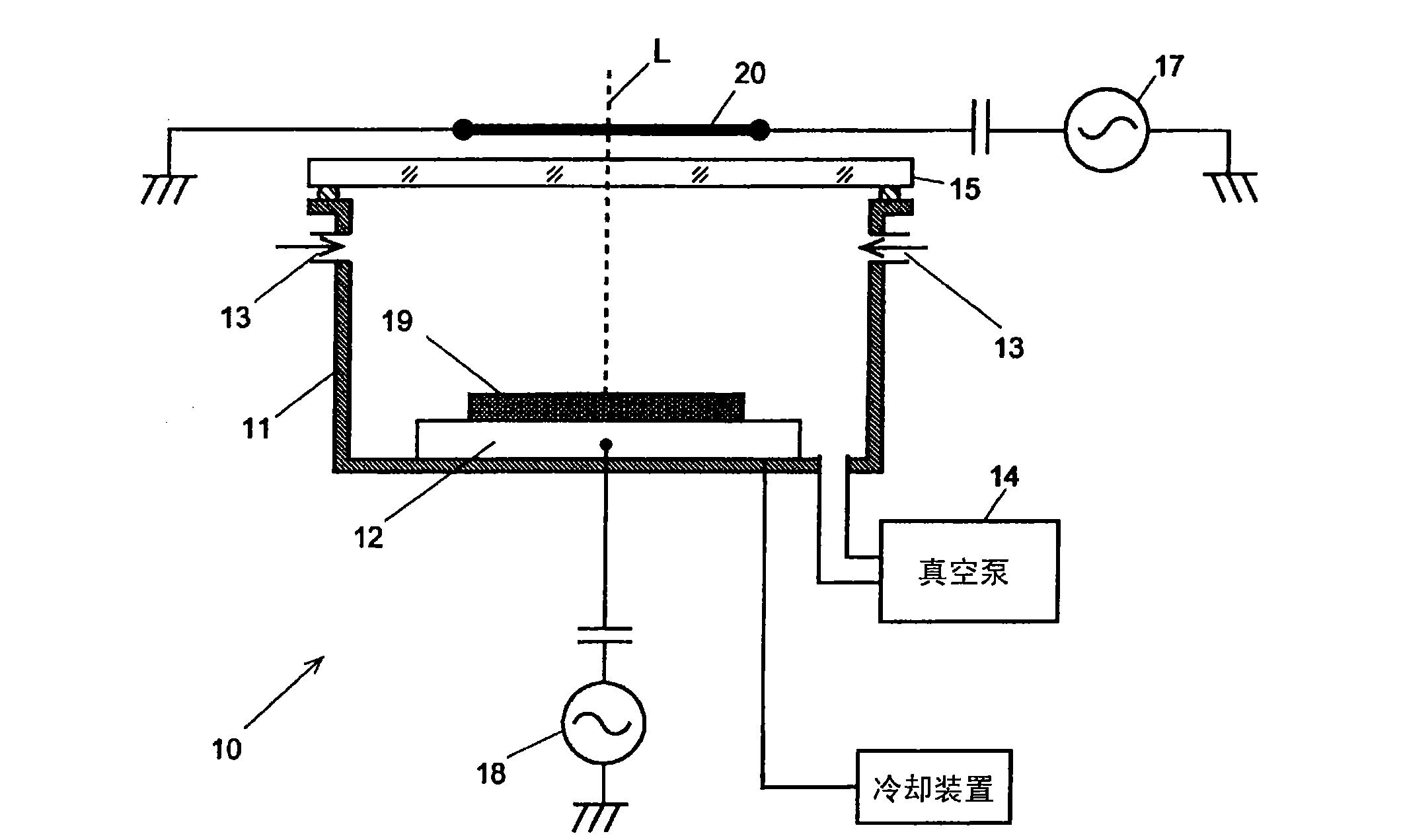
Figure 6 A schematic configuration diagram of an ICP etching apparatus 10 configured by arranging the induction coil 30 according to the third embodiment on the upper portion of the quartz plate 15 is shown. exist Figure 6 In , illustration of a gas introduction unit, a vacuum pump, a cooling device, etc. is omitted.

Figure 6 The induction coil 30 is shown, with and Figure 4 The induction coils shown have the same structure and are composed of a first induction coil 31 and a second induction coil 32, the former consisting of five coil elements and the latter consisting of three coil elements. The first and second induction coils 31 and 32 are arranged on the quartz plate 15 by using the alignment pad 34 so that the respective upper surfaces are on the same plane.

[0043]

The first and second induction coils 31 and 32 are arranged with the central axis L of the silicon wafer as a common axis among the normal lines to the surface of the silicon wafer, which is ...


PUM

PropertyMeasurementUnit
diameteraaaaaaaaaa

Abstract

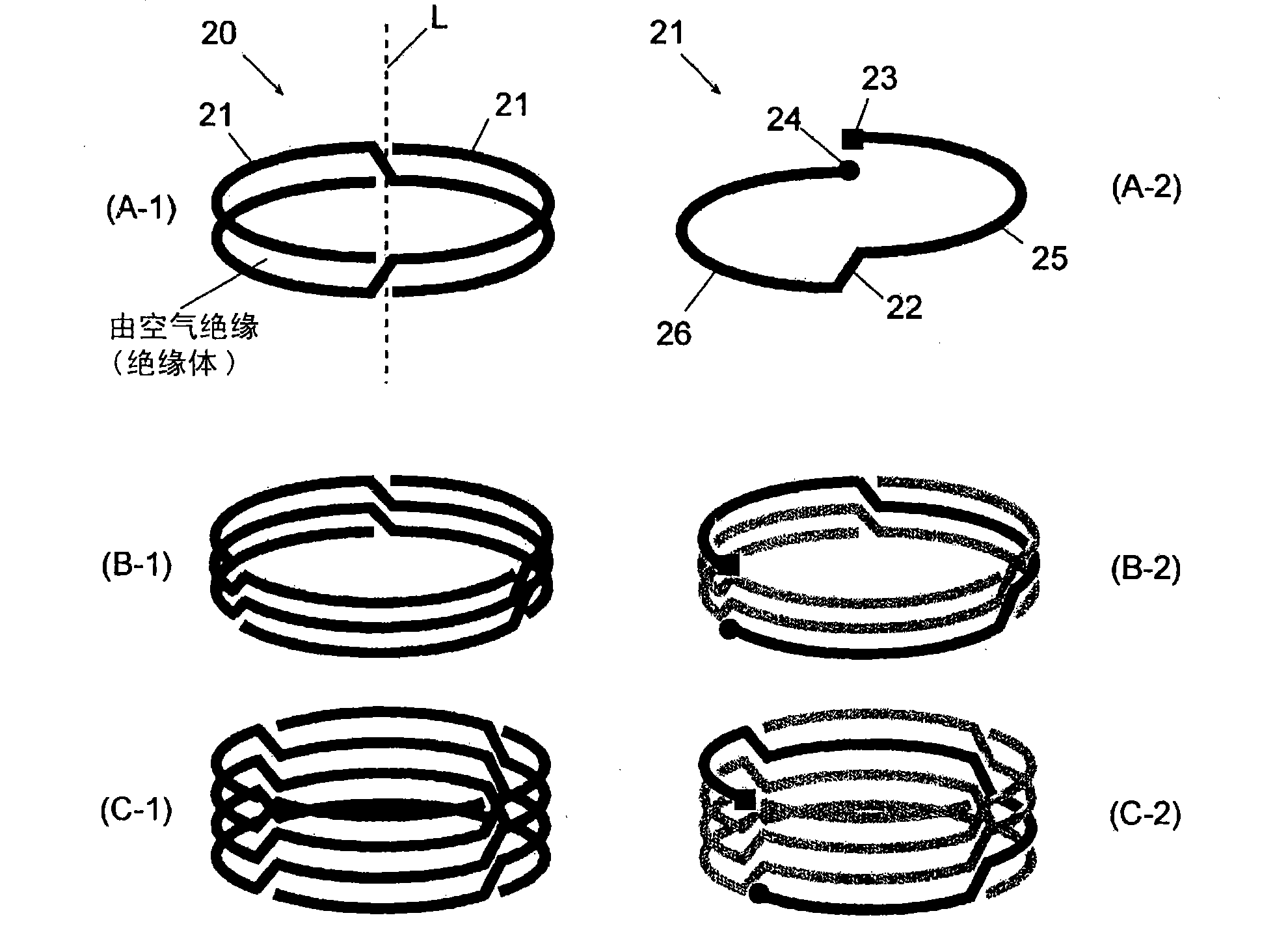
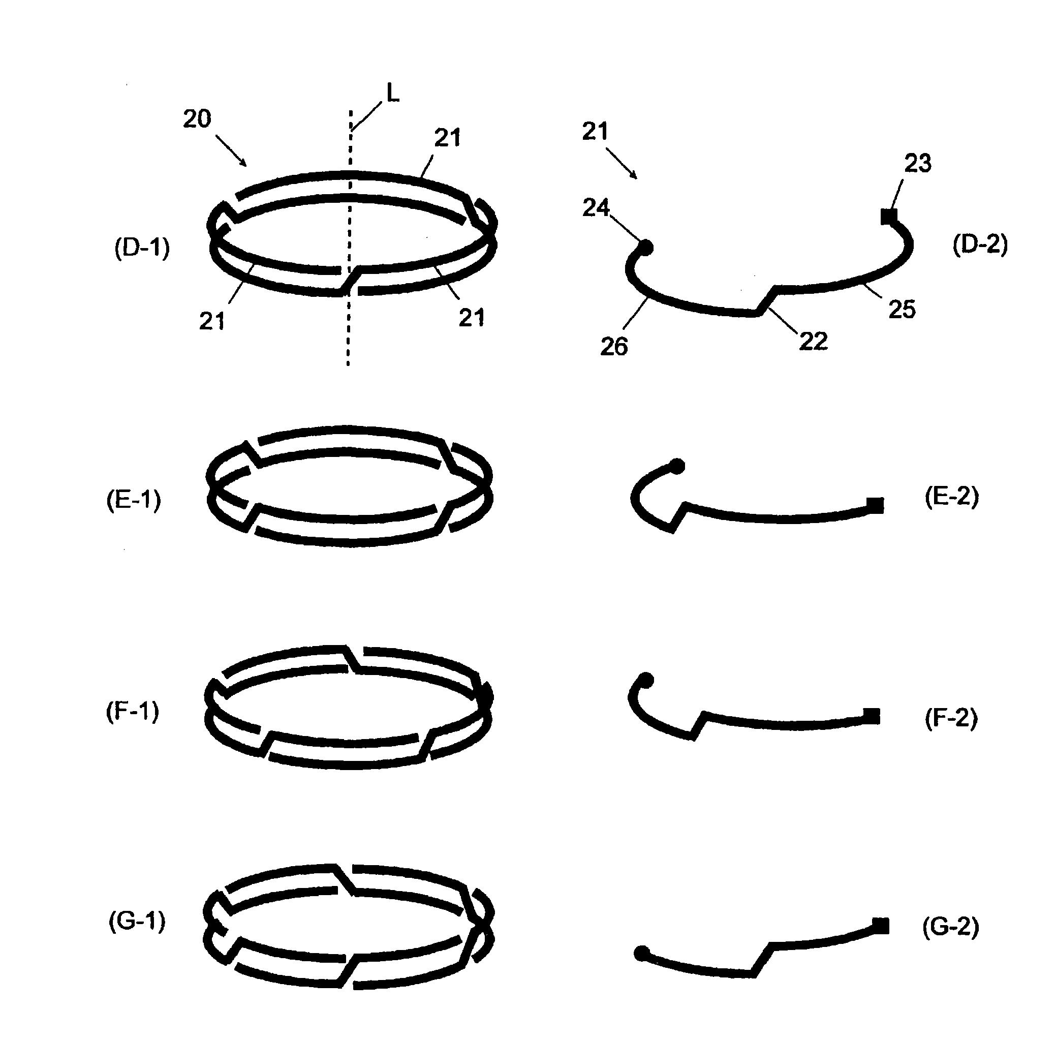
Above an object to be processed, n coil elements (n is two or more integer) having the same shape are arranged axial-symmetrically with respect to an axis which is normal of the surface of the object, and the coil elements are electrically connected parallel to one another to form an induction coil. Each coil element is a circle whose center is the above axis, has a ground end and a feed end justabove the ground end in the same point when the coil is projected onto the projection plane of the object. The coil element comprises a lower surface part having the ground end at one end, a predetermined width, and an arc shape the center angle of which is 360 DEG / n and a feed part having the feed end at one end, a predetermined width, and an arc shape, and is disposed at a level higher than that of the lower surface part, and electrically connected to the lower surface part. Such coil elements can be so combined that the feed end of one coil element is just above the ground end of another coil element.

Description

technical field [0001] The present invention relates to plasma processing devices such as plasma etching devices, plasma CVD devices, and plasma cleaning processing devices. Background technique [0002] Recent plasma process technology, like the prior art, is not limited to the field of semiconductors, but includes fields related to nanofabrication technology such as optical devices (semiconductor lasers, diodes, etc.), MEMS (gyroscopes, sensors, etc.), carbon nanotubes ・It is widely used in many fields including the medical field and the biotechnology field (microknife, sterilization, etc.). [0003] Along with the expansion of the application field, there is an increasing demand for improvement of the production efficiency, so it is natural to demand that the efficiency of the plasma processing equipment be increased. This increase in efficiency includes increase in size of samples (substrate and wafer), increase in speed of processing, high shape controllability, a...

Claims


Application Information

Patent Timeline
Patent Type & Authority Applications(China)
IPC IPC(8): H05H1/46H01L21/205H01L21/3065C23C16/507
CPCH01J37/32174H01J37/321
Inventor 仲上慎二中野博彦
Owner SAMCO INC
Learn More