Method for winding yarn on bobbin to form intersected coiled bobbin

A cross-winding and yarn technology, which is used in the field of winding the yarn onto the bobbin to form a cross-winding bobbin, can solve the problems of reducing the extraction speed and the like

CN101544318AInactive Publication Date: 2009-09-30SAURER GERMANY GMBH & CO KG
2 Cites 4 Cited by

Patent Information

Authority / Receiving Office
CN · China
Current Assignee / Owner
Publication Date
2009-09-30
Estimated Expiration
Not applicable · inactive patent

Smart Images

  • Figure 1
    Figure 1
  • Figure 2
    Figure 2
  • Figure 3
    Figure 3
Patent Text Reader

Abstract

The invention relates to a method for winding yarn (16) on a bobbin (18) to form an intersected coiled bobbin (5). The bobbin held in a bobbin creel (8) can be driven by a device (9) driven by a individual motor, and the yarn is moved on the intersected coiled bobbin (5) by using a traversing gear (10) driven by the individual motor, finally bobbin is formed gradually, wherein the taper coefficient is adopted to actuate the single motor drive unit (14) of the traversing gear (10). The taper coefficient represents the ratio of the movement rate of the yarn at the end face of the intersected coiled bobbin (5). On the cylindrical bobbin, when the intersected coiled bobbin runs, the taper coefficient is increased or reduced from 1 in yarn twisting direction. The taper is appended on the bobbin creel (8) to make the bobbin lean towards the horizontal line. The appended taper is in accordance with the asymmetrical yarn because of the change of taper coefficient at least in the direction.
Need to check novelty before this filing date? Find Prior Art

Description

technical field

[0001] The invention relates to a method for winding yarn onto a bobbin to form a cross-winding bobbin, wherein the cross-winding bobbin held in the creel is driven by a device that can be driven by a separate motor and is A traversing device driven by a separate motor displaces the yarn on the cross-winding drums to gradually form bobbins. Background technique

[0002] It is known according to the laid-open document DE 35 33 112 A1 that, when transporting away already made cylindrical cross-winding drums on a double-sided textile machine for producing cross-winding drums, the cross-winding drums manufactured on different machine sides It is rather complicated to take into account that the winding directions differ from one another in order to avoid difficulties in withdrawing the yarn starting from the top end of the cross winding drum. The winding direction cannot be discerned only from the outside of the cylindrical cross-winding drum. Thus, without know...

Examples

Embodiment Construction

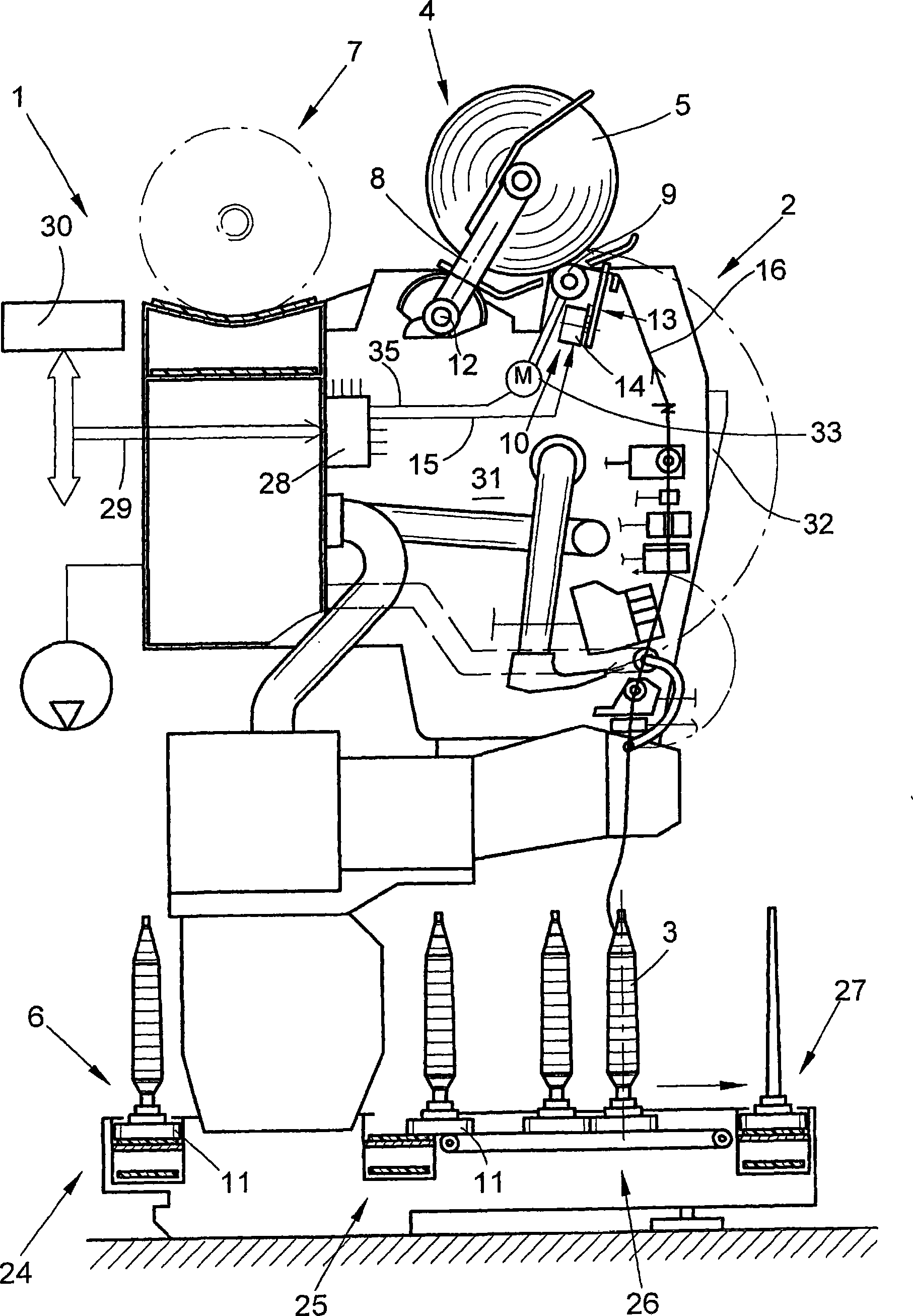
[0023] figure 1 A station 2 of a textile machine for producing cross-winding bobbins, which in the present embodiment is a so-called automatic cross-winding machine 1 , is shown schematically in side view. In station 2 of such an automatic cross-winding machine 1, the spinning bobbin 3 produced on the ring spinning machine with relatively little yarn material is rewound into a high-capacity cross-winding bobbin 5 . After its manufacture, the cross-winding bobbins 5 are handed over to the cross-winding bobbin conveyor 7 along the length of the machine by means of an automatically working service unit (not shown) and transported to the bobbin loading station arranged at the end side of the machine Wait.

[0024] Such an automatic crosswinder 1 usually also has a logistics mechanism in the form of a bobbin and bobbin delivery system 6 . In this bobbin and bobbin delivery system 6 , spinning bobbins 3 or empty bobbins are circulated on a delivery disc 11 . exist figure 1 Only...