Sludge stirring system

A stirring system and sludge technology, applied in the direction of dewatering/drying/concentrating sludge treatment, etc., can solve the problems of poor dehydration effect, large additives, inability to disperse sewage and sludge to mix evenly, etc.

Inactive Publication Date: 2009-09-30
GUANGDONG LVYOU ENVIRONMENTAL PROTECTION EQUIP CO LTD
View PDF1 Cites 14 Cited by
  • Summary
  • Abstract
  • Description
  • Claims
  • Application Information

AI Technical Summary

Problems solved by technology

[0003] This kind of sludge and garbage mixed solidification system, that is, the sludge mixing system, has the following disadvantages due to the lack of baffles: the liquid is not stirred uniformly; at the same speed, when the mixing tank is not equipped with baffles, add The amount of additives is large, and the stirring time is long. When you break the mud cake, you can see that some additives are mixed with the mud cake, and some additives remain in the mixing tank and do not participate in the reaction; the above shortcomings lead to poor dehydration effect and high production costs.
The reason is that during the stirring process, due to the linear velocity of the sewage sludge, the liquid surface forms two rotating circles, one outer circle and one inner circle; during the stirring process of sewage sludge, the outer circle is always much faster than the inner circle. The wall thickness of the outer ring formed by the surface is much smaller than that of the inner ring, and the inner ring is severa

Method used


Image

  • Sludge stirring system
  • Sludge stirring system
  • Sludge stirring system

Examples


Embodiment 1

[0030] Such as figure 1 As shown, the sludge mixing system includes a cylindrical mixing tank 1, a tank cover 2 installed on the mixing tank 1, a sludge inlet 3 provided on the tank cover 2, and a side wall of the mixing tank 1 close to the The sludge outlet 4 at the bottom of the stirring tank 1, the driving device 5 installed on the tank cover 2, the stirring shaft 6 coaxially installed with the driving device 5, fixed on the stirring shaft 6 with the stirring shaft 6 as the center of symmetry and The vertical blade shaft 7 of the stirring shaft 6, the stirring blade 8 fixed on the blade shaft 7, the baffle plate 9 installed on the inner side wall of the stirring tank 1 above its corresponding stirring blade 8, the baffle plate 9 fixed on the bottom of the stirring tank 1 bracket12.

[0031] The mixing tank 1 is made of stainless steel, with an outer diameter of 4 meters and a height of 5 meters. The stirring tank 1 and the tank cover 2 form a closed inner cavity.

[0032...

Embodiment 2

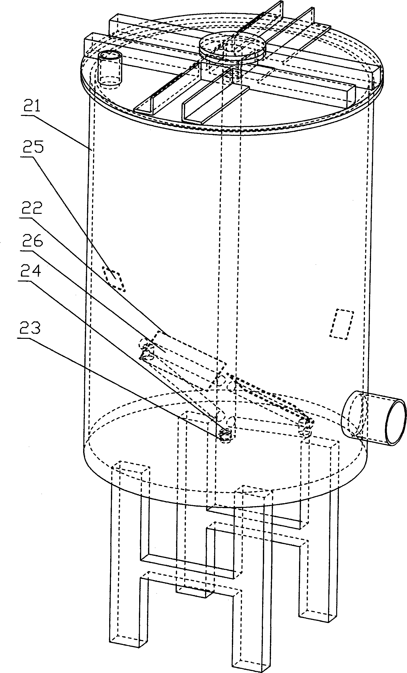
[0034] Such as figure 2 As shown, the difference from Embodiment 1 is that the stirring tank 21 is made of aluminum alloy, with an outer diameter of 1 meter and a height of 1.5 meters. The stirring blades 22 are a group, and the radial distance between the outer diameter of the blade shaft 26 and the inner wall of the stirring tank 21 is 0.08 meters. A positioning protrusion 23 is protruded from the bottom of the stirring tank 21 , and a positioning recess 24 cooperating with the positioning protrusion 23 is provided at the end of the stirring shaft.

[0035] The number of each group of baffles 25 is 2, and the vertical spacing of the corresponding stirring blades 22 is 0.3 meters; the angle at which the baffles 25 are installed is 40° with the horizontal plane; The arc surface of the stirring tank 21 is changed to an arc shape, the maximum radial width is 0.1 meters, and the length is 0.15 meters.

Embodiment 3

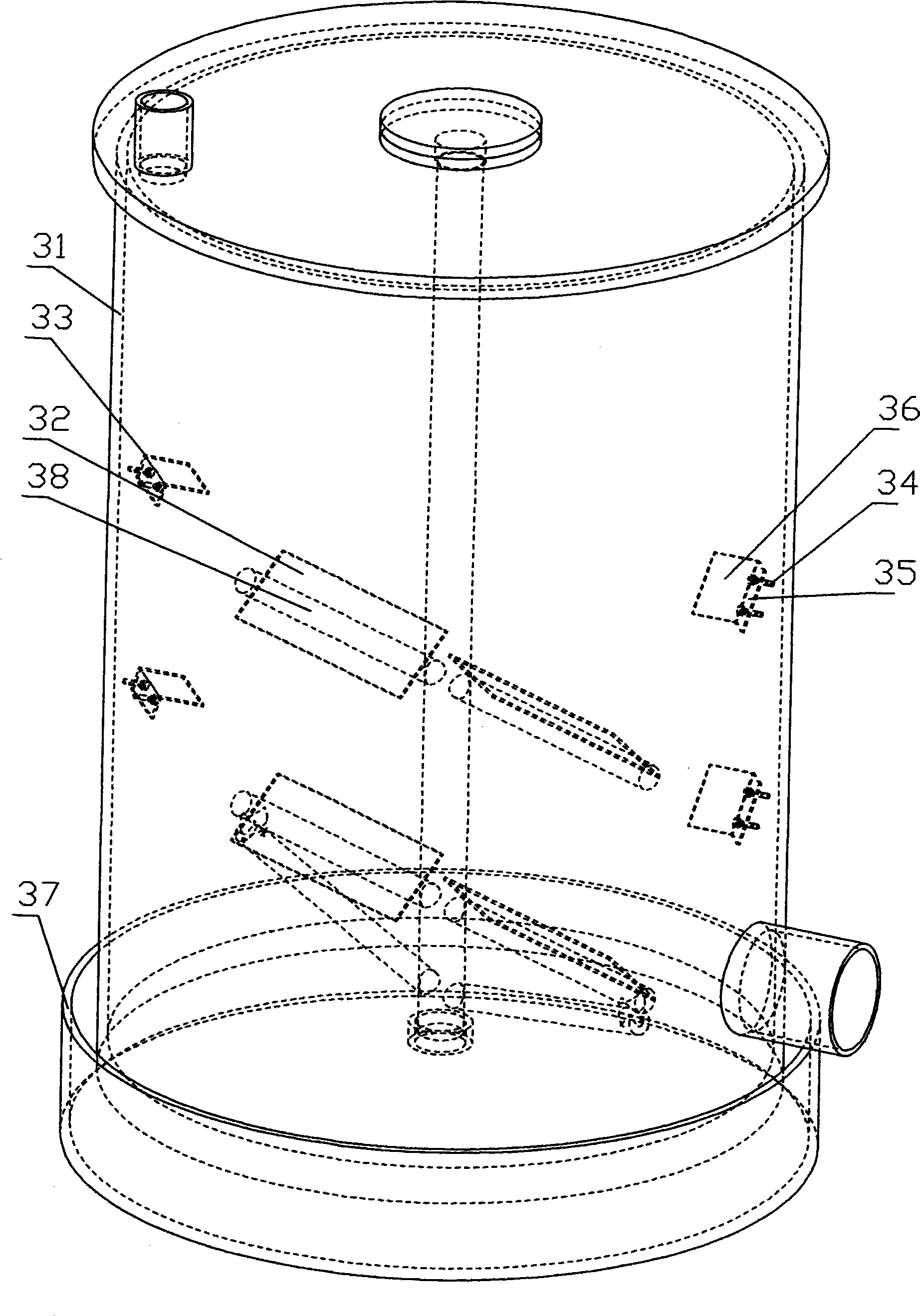
[0037] Such as image 3 As shown, the difference from Example 1 is that the stirring tank 31 is made of glass fiber reinforced plastic, with an outer diameter of 3 meters, a height of 4.3 meters, and a wall thickness of 3 centimeters.

[0038] The stirring blades 32 are a group, and the radial distance between the outer diameter of the blade shaft 38 and the inner wall of the stirring tank 31 is 0.1 meter.

[0039] The baffle 33 is L-shaped, and the vertical distance between the corresponding stirring blades 32 is 1.1 meters. The angle that the long arm 36 of baffle 33 is installed is counterclockwise with the direction of rotation of stirring blade 32, and becomes 45 ° with horizontal plane; The long arm 36 of baffle 32 is rectangular, wide 0.2 meter, long 0.3 meter.

[0040] The bottom of the stirring tank is not provided with a fixed support, but a stirring tank chassis 37 is provided, and fine sand (not shown) is housed in the stirring tank chassis 37, and the stirring ta...


PUM


Abstract

The invention discloses a sludge stirring system, comprising a stirring tank, a sludge output, a driving device, a stirring shaft arranged on the same shaft with the driving device, a stirring blade and a baffle. Every group of baffle is regularly arranged above the stirring blade of the corresponding group and has the same height with the inner side of the stirring tank. The vertical distance between the baffle and the corresponding stirring blade is more than 0.3 meter or equal to 0.3 meter. The installation direction of the baffle is opposite to the rotating direction of the stirring blade. An angle of 30 DEG to 60 DEG is kept between the baffle and the ground. The radical width of the baffle is 15 percent to 15 percent of the diameter of the stirring tank. The radical width of the baffle is more than or equal to 0.1 meter while the length of the baffle is more than or equal to 0.15 meter. The sludge stirring system has the advantages that the sludge particles are coarse, and solid-liquid separation is obvious, and insoluble additive covered in the sludge cannot be seen when opening the sludge cake, and additives not taking part in the action cannot be seen in the stirring tank. The water content of the sludge cake after dehydration is less than 60 percent.

Description

technical field [0001] The invention relates to a sludge stirring system for uniformly stirring sludge. Background technique [0002] The existing sludge mixing system, such as the utility model patent No. 200720069024.8, discloses a sludge and garbage mixing solidification system, including a mixing tank, a material inlet, a material outlet, and a number of stirring shafts in the mixing tank , a number of stirring arms are fixed on the stirring shaft, at least one stirring blade is installed at the front end of each stirring arm, and the same number of side blades as the number of stirring blades is installed at the rear end of each stirring arm. [0003] This kind of sludge and garbage mixed solidification system, that is, the sludge mixing system, has the following disadvantages due to the lack of baffles: the liquid is not stirred uniformly; at the same speed, when the mixing tank is not equipped with baffles, add The amount of additives is large, and the mixing time is...

Claims


Application Information

Patent Timeline
IPC IPC(8): C02F11/14
Inventor 古耀坤曾智权
Owner GUANGDONG LVYOU ENVIRONMENTAL PROTECTION EQUIP CO LTD
Why Eureka
Try Eureka