Check patentability & draft patents in minutes with Patsnap Eureka AI!

Backlight unit

A technology of backlight unit and light source, applied in optical elements, light guides, optics, etc., can solve the problems of diffuse light generation, brightness deterioration, deformation, and bending of the backlight unit.

Inactive Publication Date: 2009-09-30
TOYODA GOSEI CO LTD
View PDF2 Cites 3 Cited by
  • Summary
  • Abstract
  • Description
  • Claims
  • Application Information

AI Technical Summary

Problems solved by technology

However, such a backlight unit using a large light guide plate and an optical sheet has a problem that when the backlight unit is used in an environment where the temperature difference varies greatly, such as inside a vehicle, due to the expansion and contraction of the light guide plate and the optical sheet, The backlight unit may be bent and deformed
In other words, when large light guide plates and optical sheets are used, there arises a problem that these members expand to interfere with each other or other adjacent members such as support plates, and therefore, sufficient measures need to be taken to prevent such problems
[0006] In addition, when the gap is made large, foreign matter such as dust is likely to penetrate into the gap
The infiltration of foreign matter is undesirable because it has an effect on the optical characteristics of the backlight unit, which may lead to the generation of stray light and deterioration of brightness

Method used


Image

  • Backlight unit
  • Backlight unit
  • Backlight unit

Examples


Embodiment Construction

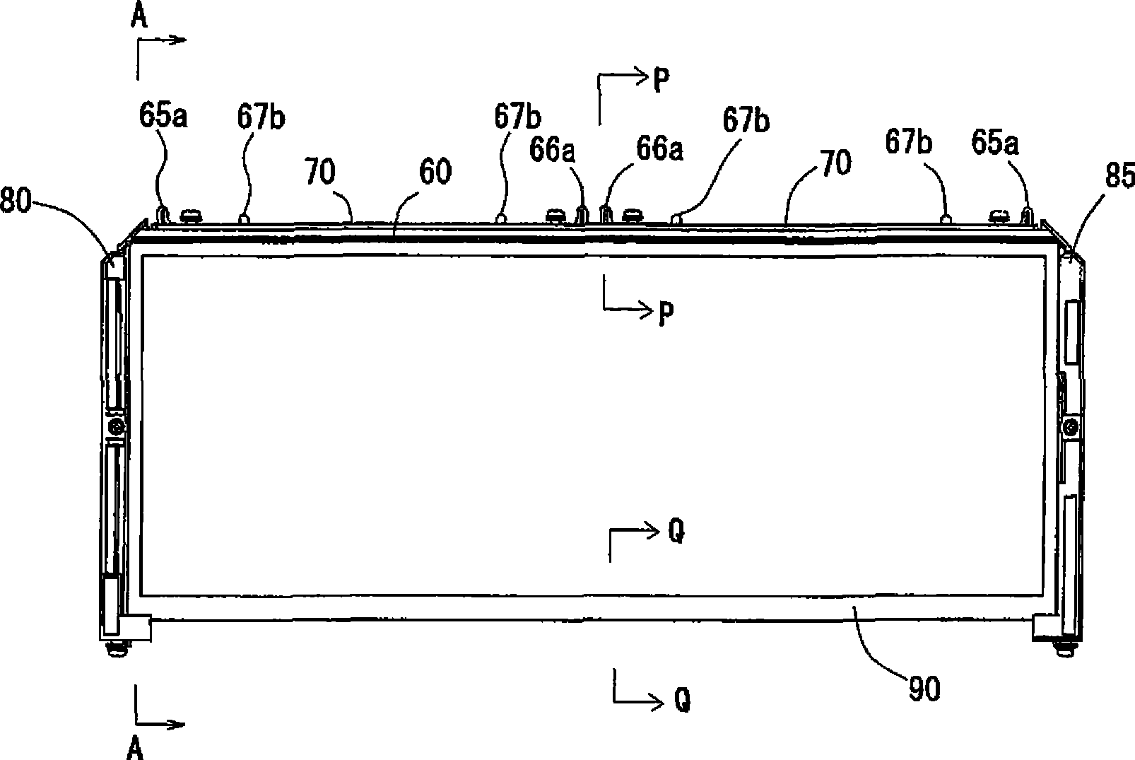
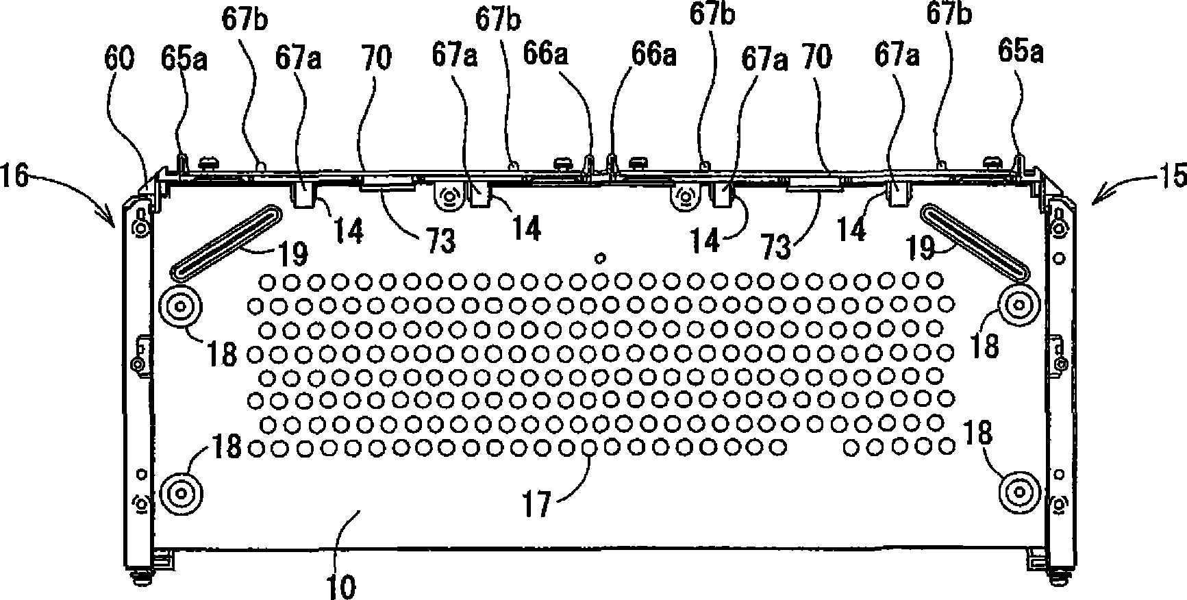
[0081] The present invention will be described in detail below with reference to the accompanying drawings. figure 1 is an exploded perspective view of the backlight unit 1 according to one embodiment of the present invention. Figure 2 to Figure 7 These are a front view, a rear view, a left view, a right view, a plan view and a bottom view of the backlight unit 1, respectively. The backlight unit 1 includes a shield cover (support plate) 10, a reflection sheet 20, a light guide (light guide plate) 30, a diffusion sheet 40, a vertical eye prism sheet 50, a horizontal eye prism sheet 51, an upper holder (maintaining member) 60, A printed circuit board assembly 70 , a left holder 80 , a right holder 85 , and a TFT holder (liquid crystal panel holding member) 90 . In the backlight unit 1 , the reflection sheet 20 , the light guide 30 , the diffusion sheet 40 , the vertical eye prism sheet 50 and the horizontal eye prism sheet 51 are sequentially stacked in the front of the shield ...


PUM


Abstract

To provide a backlight unit for use in a liquid crystal display device and so on, which is capable of overcoming a problem of interference due to expansion and contraction of a light guide plate and an optical sheet and preventing a strange noise by clicking, a backlight unit includes a support plate, a light guide plate that is disposed in the front side of the support plate and emits light, which is introduced from a light source through the end side of the light guide plate, through the front side of the light guide plate, an optical sheet that is disposed in the front side of the light guide plate, and a liquid crystal panel maintenance member that is disposed in the front side of the optical sheet, wherein the light guide plate and the liquid crystal panel maintenance member hold and fix the optical sheet at one point.

Description

technical field [0001] The present invention relates to a backlight unit used in liquid crystal display devices and the like. Background technique [0002] Backlight units of liquid crystal display devices are generally classified into an edge light type and a direct light type. The edge light type is mainstream for relatively small-sized liquid crystal display devices used in car navigators, mobile phones, and the like. In the edge light type backlight unit, the light introduced into the photoconductor through the end of the photoconductor is emitted from the front surface of the photoconductor, and the luminous flux is adjusted by means of the optical sheet to obtain desired surface light. A light guide plate or an optical sheet is fixed (maintained) on a support plate or a case (hereinafter referred to as a "support plate, etc."), but in conventional backlight units, the use of through holes provided in the optical sheet by means of screws, etc., is adopted. A method of...

Claims


Application Information

Patent Timeline
IPC IPC(8): G02F1/1335G02F1/13
CPCG02B6/0088
Inventor 服部德文带刀庆真
Owner TOYODA GOSEI CO LTD
Features
  • R&D
  • Intellectual Property
  • Life Sciences
  • Materials
  • Tech Scout
  • Unparalleled Data Quality
  • Higher Quality Content
  • 60% Fewer Hallucinations
Learn More