Memory control apparatus, memory control method and information processing system

A technology of a control device and a control method, applied in memory systems, micro-control devices, electrical digital data processing, etc., can solve the problems of increasing delay, hindering the improvement of information processing system performance, etc. Effect

Active Publication Date: 2009-09-30
FUJITSU LTD
View PDF1 Cites 6 Cited by
  • Summary
  • Abstract
  • Description
  • Claims
  • Application Information

AI Technical Summary

Problems solved by technology

Transmitting fetch response data along this long-distance path is another source of increased latency and impedes improvements in information handling system performance

Method used


Image

  • Memory control apparatus, memory control method and information processing system
  • Memory control apparatus, memory control method and information processing system
  • Memory control apparatus, memory control method and information processing system

Examples


Embodiment Construction

[0045] Hereinafter, embodiments of the present invention will be described with reference to the drawings.

[0046] [1] Embodiment of the present invention

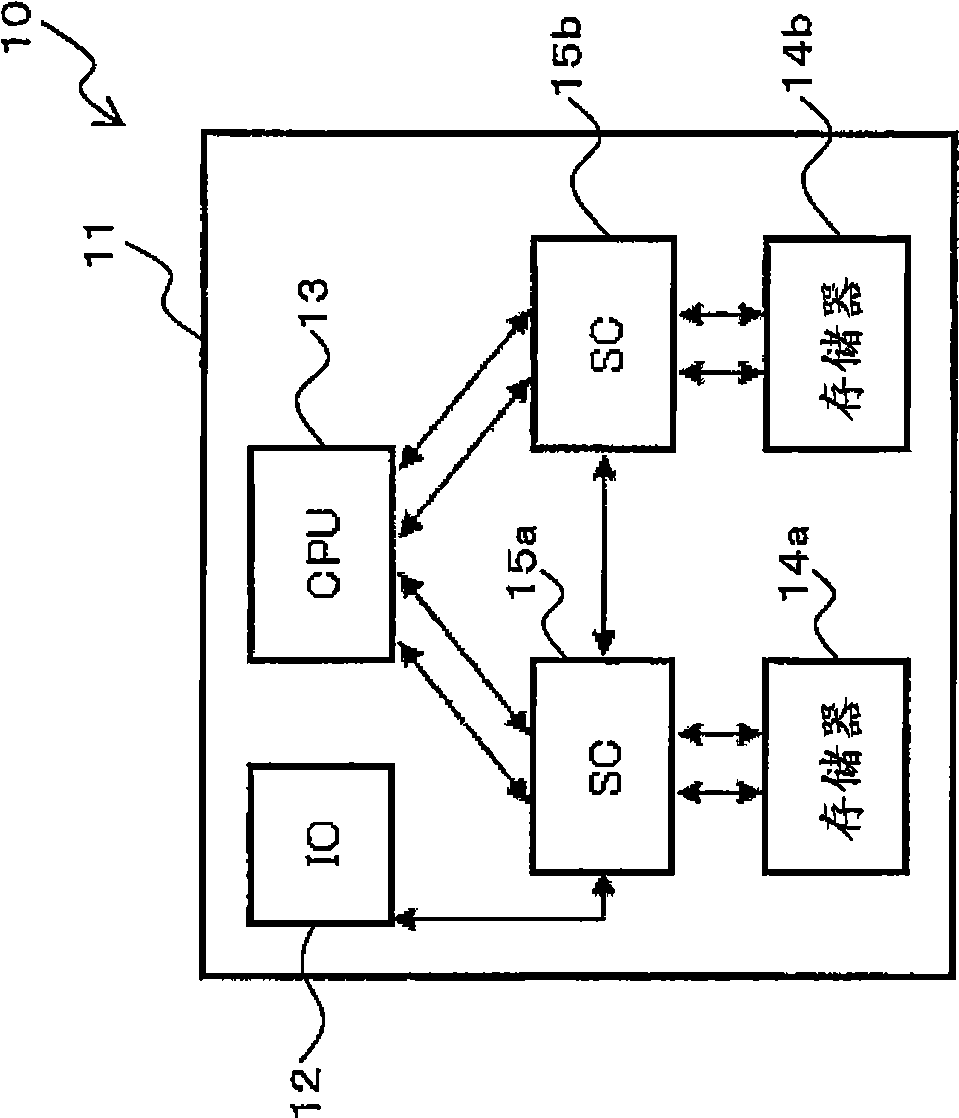
[0047] figure 1 is a block diagram schematically showing a structural example of the information processing system 10 according to the embodiment of the present invention.

[0048] An information processing system 10 according to an embodiment of the present invention includes a system board 11 composed of an integrated circuit, such as figure 1 As shown, an I / O (input / output: IO) unit (external input / output controller) 12, a CPU (central processing unit: processor) 13, a plurality of (in figure 1 In the case shown two) memories (main storage units) 14a, 14b and a plurality (in figure 1 In the illustrated case two) system controllers (SC: memory control unit; system on chip) 15a, 15b.

[0049] The I / O unit 12 is a device for controlling transmission and reception of signals to and from devices outside the system b...


PUM


Abstract

A memory control apparatus, a memory control method and an information processing system are disclosed. Fetch response data retrieved from a main storage unit (14a) is received, while bypassing a storage unit (19), by a first port (18) in which the received fetch response data can be set. The fetch response data retrieved from the main storage unit (14a), if unable to be set in the first port (18), is set in a second port (20) through the storage unit (19). A send-out control unit (22) performs priority control operation to send out, in accordance with a predetermined priority, the fetch response data set in the first port (18) or the second port (20) to the processor (13). As a result, the latency is shortened from the time when the fetch response data arrives to the time when the fetch response data is sent out toward the processor in response to a fetch request from the processor.

Description

technical field [0001] Embodiments disclosed herein are techniques for obtaining fetch response data from a main storage unit in response to a fetch request of a processor and sending the fetch response data to a processor. Background technique [0002] In general, from the viewpoint of obtaining high speed and high performance of an information processing system, integrated circuits mounted on its system board are required to process and transmit / receive packets in a shorter time (see, for example, Japanese Patent Application Laid-Open No. 62 -245462). [0003] Figure 8 is a block diagram schematically showing a structural example of a system board of a conventional information processing system, and Figure 9 is a block diagram schematically showing an example of the structure of its system controller. [0004] A conventional information handling system 80 includes, for example, a system board 81 such as Figure 8 As shown, an I / O (input / output: IO) unit (external input...

Claims


Application Information

Patent Timeline
Patent Type & Authority Applications(China)
IPC IPC(8): G06F13/18
CPCG06F13/1673G06F13/1642G06F3/06G06F9/24G06F12/00
Inventor 草地宗太
Owner FUJITSU LTD
Why Eureka
Try Eureka