
Novel intelligent antenna and method for realizing same

A smart antenna, a new type of technology, applied in antennas, antenna arrays, diversity/multi-antenna systems, etc., can solve the problems of calibration network manufacturing errors, increased cost of antenna arrays, and reduced calibration accuracy, so as to reduce antenna costs and solve engineering installation problems. the difficult effect of

Active Publication Date: 2009-09-30
成都芯通软件有限公司
View PDF5 Cites 7 Cited by
  • Summary
  • Abstract
  • Description
  • Claims
  • Application Information

AI Technical Summary

Problems solved by technology

[0007] 1. To realize the multi-antenna unit antenna array of the smart antenna, the distance between each antenna unit must be kept the same, and it must not exceed the half-wavelength of the highest operating frequency. Install;
[0008] 2. The distance between each antenna unit is relatively close, and the correlation of radio wave propagation is strong, so it is difficult to obtain space diversity gain;
[0009] 3. Smart antennas and multiple-input multiple-output (MIMO) antennas are difficult to implement in the same antenna array, which is a big problem for the implementation of post-3G (such as LTE) and 4G mobile communications
[0012] 4. A calibration network must be used, resulting in an increase in the cost of the antenna array;
[0013] 5. The manufacturing error of the calibration network is unavoidable, which will lead to calibration errors and reduce the calibration accuracy;
[0014] 6. For smart antennas with each antenna element arrangement method, a corresponding calibration network must be designed;
[0015] 7. It is impossible to use a new type of smart antenna with arbitrary arrangement of antenna units, and it is impossible to solve the goal of implementing smart antennas and multiple-input multiple-output (MIMO) antennas in the same antenna array in the future. The implementation of mobile communication is a big problem

Method used


Image

  • Novel intelligent antenna and method for realizing same
  • Novel intelligent antenna and method for realizing same
  • Novel intelligent antenna and method for realizing same

Examples


Embodiment Construction

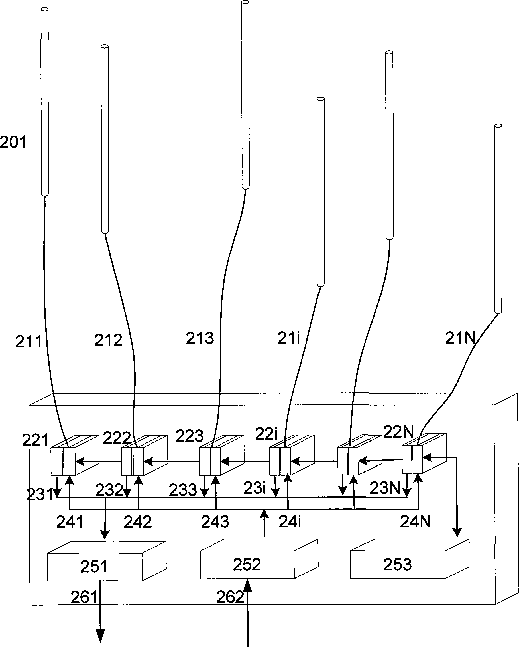
[0050] The present invention will be described in detail by taking a smart antenna system used by a wireless base station of a TDD (such as TD-SCDMA) system as described in the figure below as an embodiment.

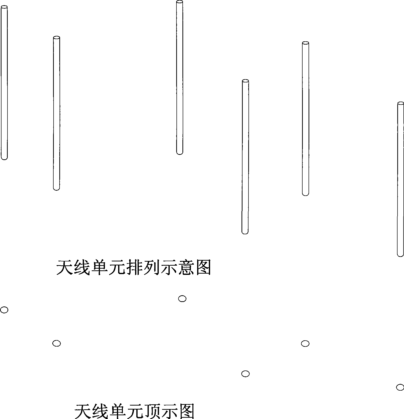
[0051] figure 2 A side view and a top view of an antenna array composed of N antenna elements arranged arbitrarily and at any distance are shown in the present invention. In the land mobile communication environment, only the receiving and transmitting beams on the horizontal plane are considered, so only the antenna arrangement on the horizontal plane is considered. The antenna array works in a time division multiple access (TDD) mobile communication system, that is, each antenna unit receives and transmits at different times. For working in frequency division multiple access (FDD) mobile communication system,

[0052] Then two antenna arrays are required to work at different frequencies to receive and transmit respectively. However, regardless of the time division ...


PUM


Abstract

The invention provides a novel intelligent antenna and a method for realizing the same. The method comprises the following steps that: antenna units which are used to form the intelligent antenna are randomly arranged according to random distance without needing to be equidistantly arranged according to the distance not exceeding half wavelength; the figuration of receiving a wave beam is realized by measuring the amplitude and the phase of a signal received by each receiving chain circuit and synthesizing the signal received by each chain circuit in a needed mode. The figuration of transmitting the wave beam is realized by focusing the signal transmitted by each antenna unit on a terminal. A multi-antenna array is controlled by software to be operated into an intelligent antenna, a diversity antenna or a multi-input and multi-output (MIMO) antenna. The novel intelligent antenna does not need mounting a transceiver especially for calibration and a special calibration chain circuit. A multifunctional multi-antenna system realization method is provided for wireless base stations of 3G, beyond 3G and 4G mobile communication networks.

Description

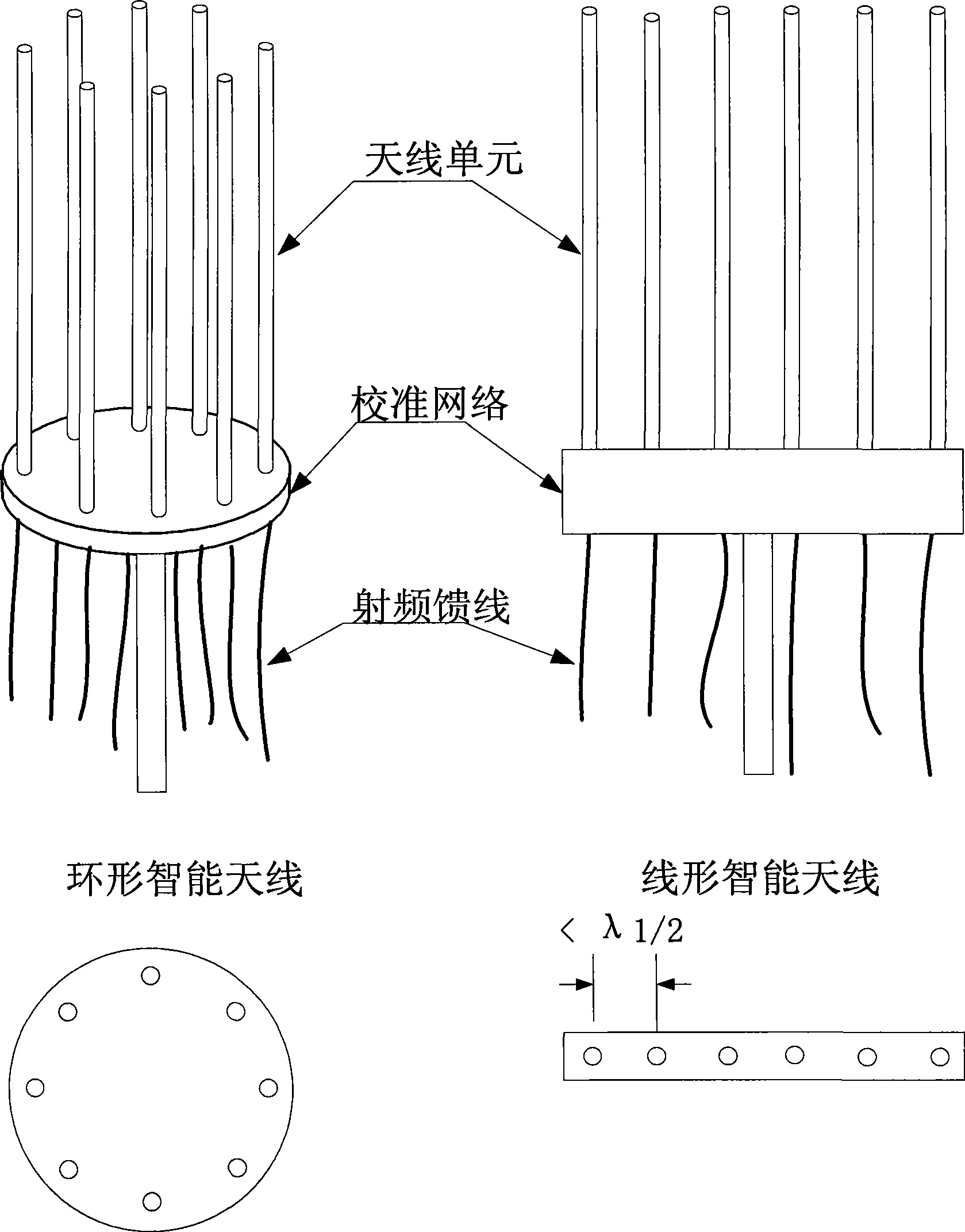
technical field [0001] The present invention relates to the technical field of mobile communication, and more precisely relates to a new type of smart antenna in the third generation mobile communication system and its realization method. Background technique [0002] The use of smart antennas in the TD-SCDMA third-generation mobile communication (3G) system has become a consensus in the industry and has been applied on a large scale. [0003] A schematic diagram of a typical smart antenna array is shown in figure 1 : An 8-element loop smart antenna and a 6-element linear smart antenna. They all consist of multiple antenna elements mounted on the same plane, a calibration network and connected RF feeder interfaces. From the top view, these antenna elements are neatly arranged in a circle (left) or a straight line (right) with a distance of no more than half a wavelength. The above two smart antennas are commercially available and widely used in the third generation mobile...

Claims


Application Information

Patent Timeline
Patent Type & Authority Applications(China)
IPC IPC(8): H01Q21/00H04B7/04H04B17/00H01Q3/34H04B17/12
Inventor 李睿
Owner 成都芯通软件有限公司
Learn More