Vertical wind power generator with motor startup mode

A technology of wind power generator and starting method, which is applied in the direction of controlling the generator, controlling the generator and electrical components through the change of the magnetic field, and can solve the problems such as the difficulty of starting the generator, so as to improve the static stability, reduce the degree of failure loss, The effect of improving transient stability

Inactive Publication Date: 2009-09-30
GUANGZHOU YATU NEW ENERGY TECH
View PDF5 Cites 3 Cited by
  • Summary
  • Abstract
  • Description
  • Claims
  • Application Information

AI Technical Summary

Problems solved by technology

[0003] The technical problem to be solved by the present invention is to provide a vertical wind power generator with a motor starting method, which greatly improves the power generation efficiency of the generator and solves the problem of difficulty in starting the generator

Method used


Image

  • Vertical wind power generator with motor startup mode
  • Vertical wind power generator with motor startup mode
  • Vertical wind power generator with motor startup mode

Examples


Embodiment 1

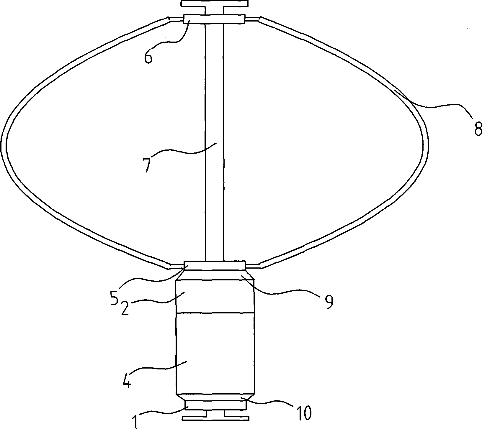
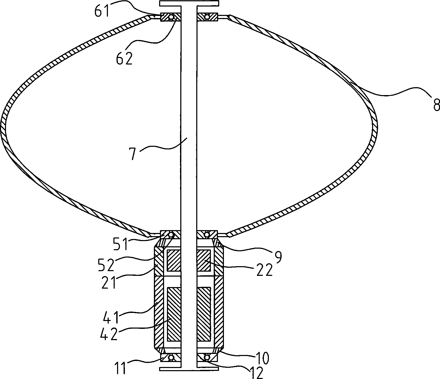
[0041] Such as figure 1 , 2 As shown, a vertical wind power generator with a motor starting method includes a tower column and a vertical wind power generation unit located on the tower column 7, and the vertical wind power generation unit includes a first bearing 1, a generator 4, a second bearing 5. The third bearing 6 and the blade 8. The first bearing 1 includes a first bearing outer ring 11 and a first bearing inner ring 12. The second bearing 5 includes a second bearing outer ring 51 and a second bearing inner ring 52. The third bearing 6 includes a first bearing outer ring 51 and a second bearing inner ring 52. Three bearing outer rings 61 and a third bearing inner ring 62 . The first bearing inner ring 12 , the second bearing inner ring 52 and the third bearing inner ring 62 are fixedly sleeved on the tower column 7 . The lower end of the blade 8 is fixedly connected to the second bearing outer ring 51 , and the upper end of the blade 8 is fixedly connected to the t...

Embodiment 2

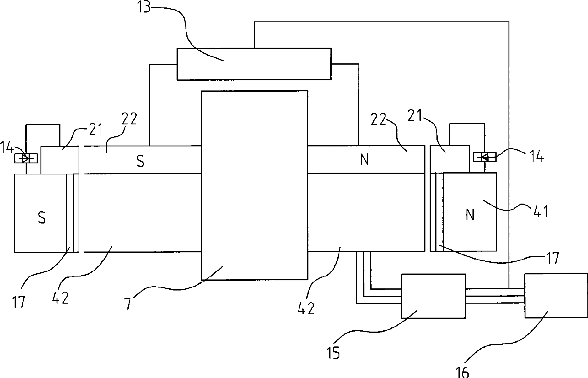
[0050] Such as Figures 4 to 6 As shown, a vertical wind power generator with a motor starting method includes a tower column 7 and two vertical wind power generation units located on the tower column 7, and the two vertical wind power generation units are vertically distributed up and down. The vertical wind power generation unit includes a first bearing 1 , a generator 4 , a second bearing 5 , a third bearing 6 , and blades 8 . The first bearing 1 includes a first bearing outer ring 11 and a first bearing inner ring 12. The second bearing 5 includes a second bearing outer ring 51 and a second bearing inner ring 52. The third bearing 6 includes a first bearing outer ring 51 and a second bearing inner ring 52. Three bearing outer rings 61 and a third bearing inner ring 62 . The lower end of the blade 8 is fixedly connected to the second bearing outer ring 51 , and the upper end of the blade 8 is fixedly connected to the third bearing outer ring 61 . The generator 4 is an out...


PUM


Abstract

The present invention provides a vertical wind power generator with motor startup mode, comprising a column and one or more vertical wind power generation units on the column. The generator is equipped with an excitation system and a damper system. The excitation system comprises an excitation controller, an exciter, a rotary rectifier, an electric network, and a two-way converter; the damper system comprises a damping winding, a two-way converter, and an electric network; wherein, the exciter is connected to the generator rotor, the excitation controller is connected to the stator winding of the exciter, the rotor winding of the exciter is connected to the generator rotor winding via the rotary rectifier, the excitation controller is connected to the electric network, the electric network is connected to the two-way converter, and the two-way converter is connected to the generator stator winding; the damping winding is mounted on the generator rotor. At low speeds, the generator can operate in electrodynamic mode, so that the difficulty in generator startup is settled. During normal operation, the generator can operate at variable speeds at constant frequency.

Description

technical field [0001] The invention relates to the field of vertical wind power generators, in particular to vertical wind power generators with a motor starting mode. Background technique [0002] The excitation system is an important part of the entire generator system. The exciter is equivalent to a small generator and is used to provide DC excitation current for the generator rotor winding. The excitation winding of the generator rotor is fed with DC current to generate a nearly sinusoidal distributed magnetic field (called the rotor magnetic field), and its effective excitation flux intersects with the stationary armature winding. When the rotor rotates, the rotor magnetic field rotates together with it. Every time a revolution is made, the magnetic lines of force cut each phase winding of the stator in sequence, and a three-phase AC potential is induced in the three-phase stator winding. The excitation system has a great influence on the safe and stable operation of ...

Claims


Application Information

Patent Timeline
Patent Type & Authority Applications(China)
IPC IPC(8): H02P9/00H02P9/14
Inventor 邓允河
Owner GUANGZHOU YATU NEW ENERGY TECH
Why Eureka
Try Eureka