Eureka AIR delivers breakthrough ideas for toughest innovation challenges, trusted by R&D personnel around the world.

Transport system and producing method of sub-vacuum duct

A technology for vacuum pipelines and transportation systems, applied in tunnel systems, roads, rails, etc., can solve the problems of large vacuum extraction projects, inconvenient passage of passengers, and poor passage sealing, achieving good sealing effect and eliminating the need for entry and exit. channel, low cost effect

Inactive Publication Date: 2011-04-13
谢建新
View PDF3 Cites 0 Cited by
  • Summary
  • Abstract
  • Description
  • Claims
  • Application Information

AI Technical Summary

Problems solved by technology

[0003] The technical problem to be solved by the present invention is to provide a sub-vacuum pipeline transportation system and a manufacturing method of the sub-vacuum pipeline to solve the problems in the above-mentioned prior art that the project of pumping and making vacuum is large, the cost is high, and the channel is not tightly sealed. Inconvenience for Passengers

Method used


Image

  • Transport system and producing method of sub-vacuum duct
  • Transport system and producing method of sub-vacuum duct
  • Transport system and producing method of sub-vacuum duct

Examples


Embodiment 1

[0044] Example 1: Magnetic levitation sub-vacuum pipeline transportation system

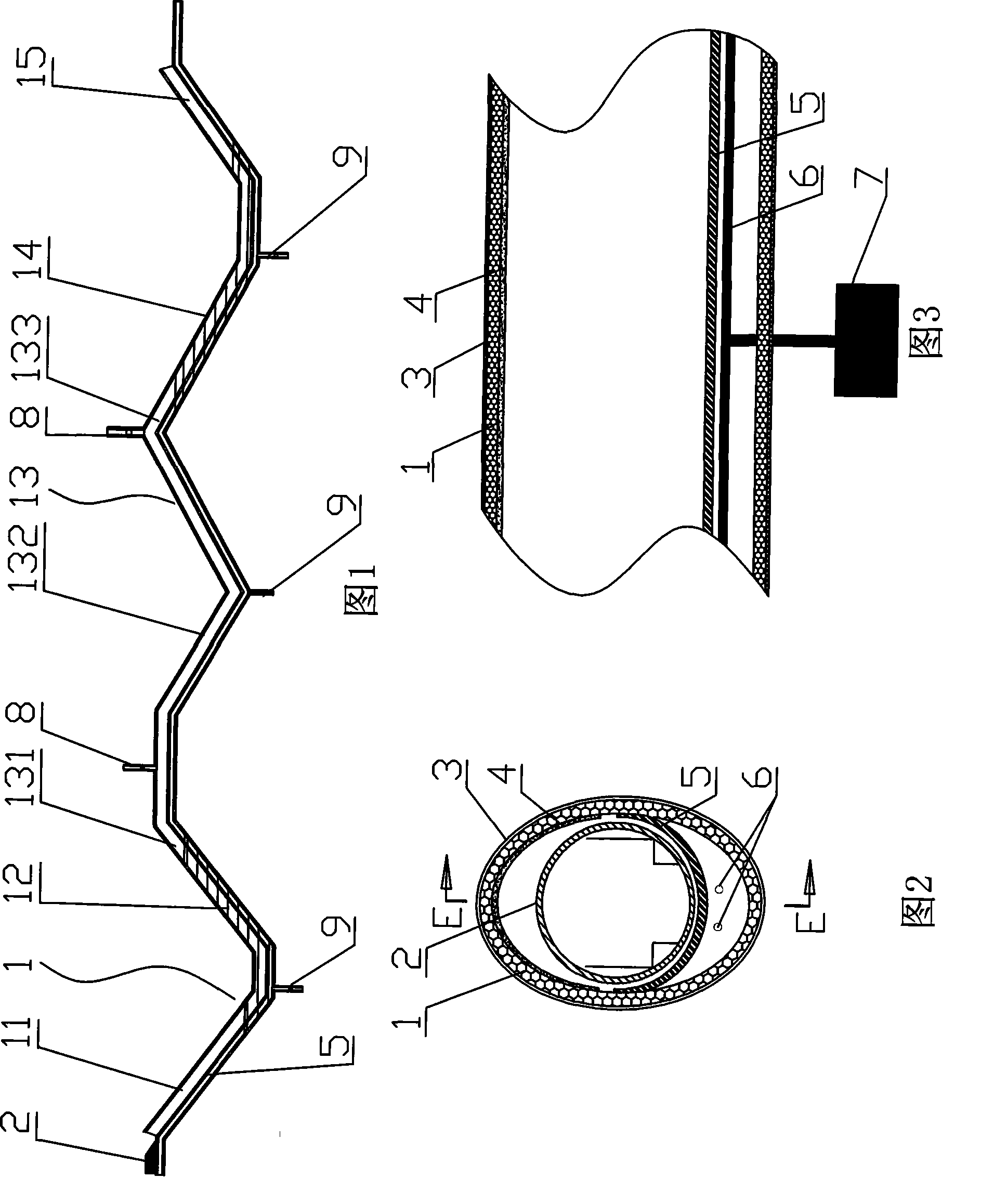
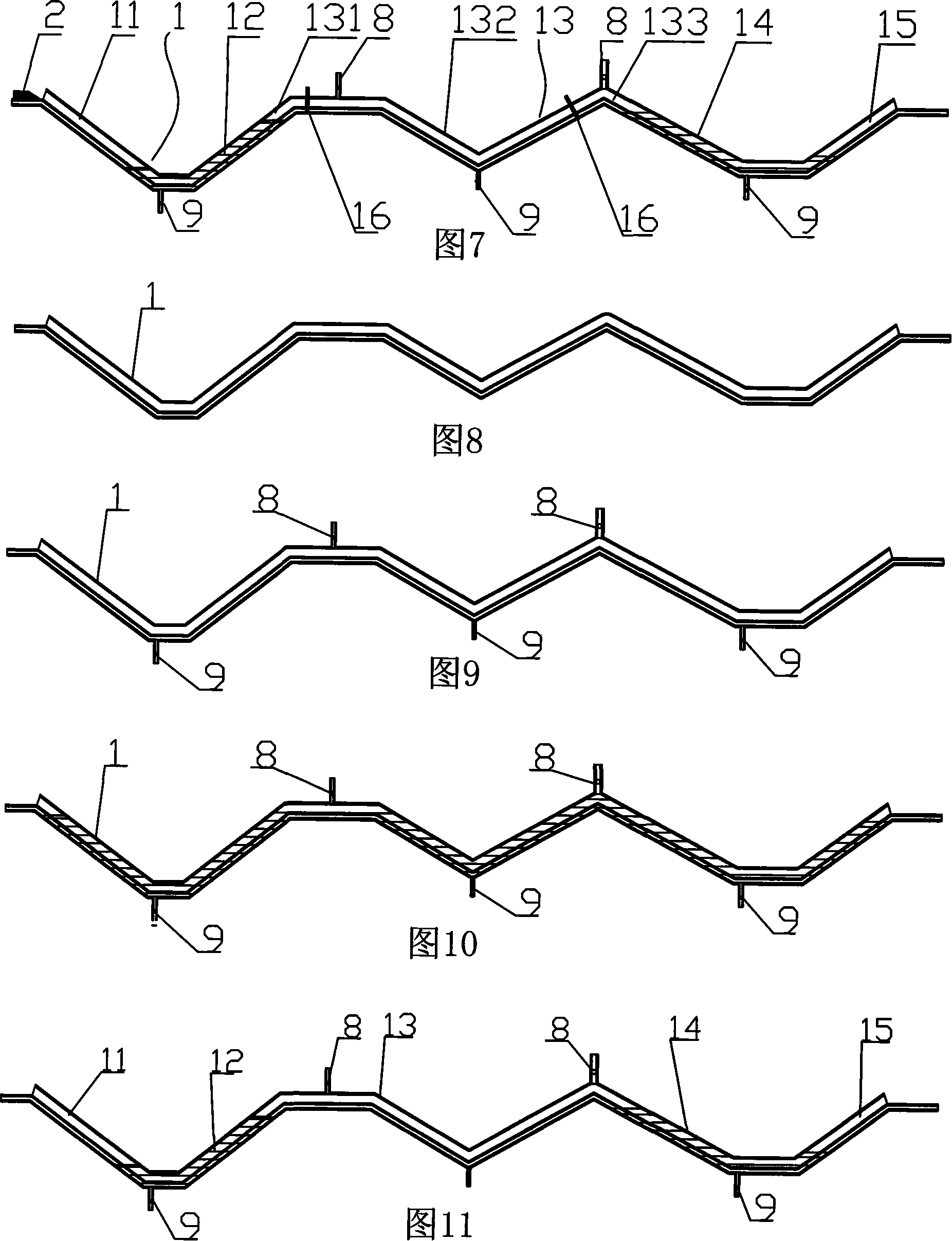
[0045] As shown in Figures 1 to 3, a magnetically levitated sub-vacuum pipeline transportation system includes a sub-vacuum pipeline 1 and a closed magnetic levitation train 2, a life support system is installed in the train body 2, and the sub-vacuum Pipeline 1 is composed of five parts, which are successively connected, the inlet atmospheric pressure downhill section 11, the inlet water sealing section 12, the sub-vacuum section 13, the outlet water sealing section 14 and the outlet atmospheric pressure uphill section 15 (see Figure 1) , the sub-vacuum section 13 is divided into a sub-vacuum ascending section 131, a sub-vacuum middle section 132 and a sub-vacuum descending section 133, wherein the sub-vacuum middle section 132 is a curve shape undulating with the terrain; 11 is connected to the sub-vacuum ascending section 131 through the inlet water-sealed section 12, and the outlet atmospheri...

Embodiment 2

[0055] Embodiment 2: A magnetic levitation sub-vacuum pipeline transportation system with valves in the pipeline

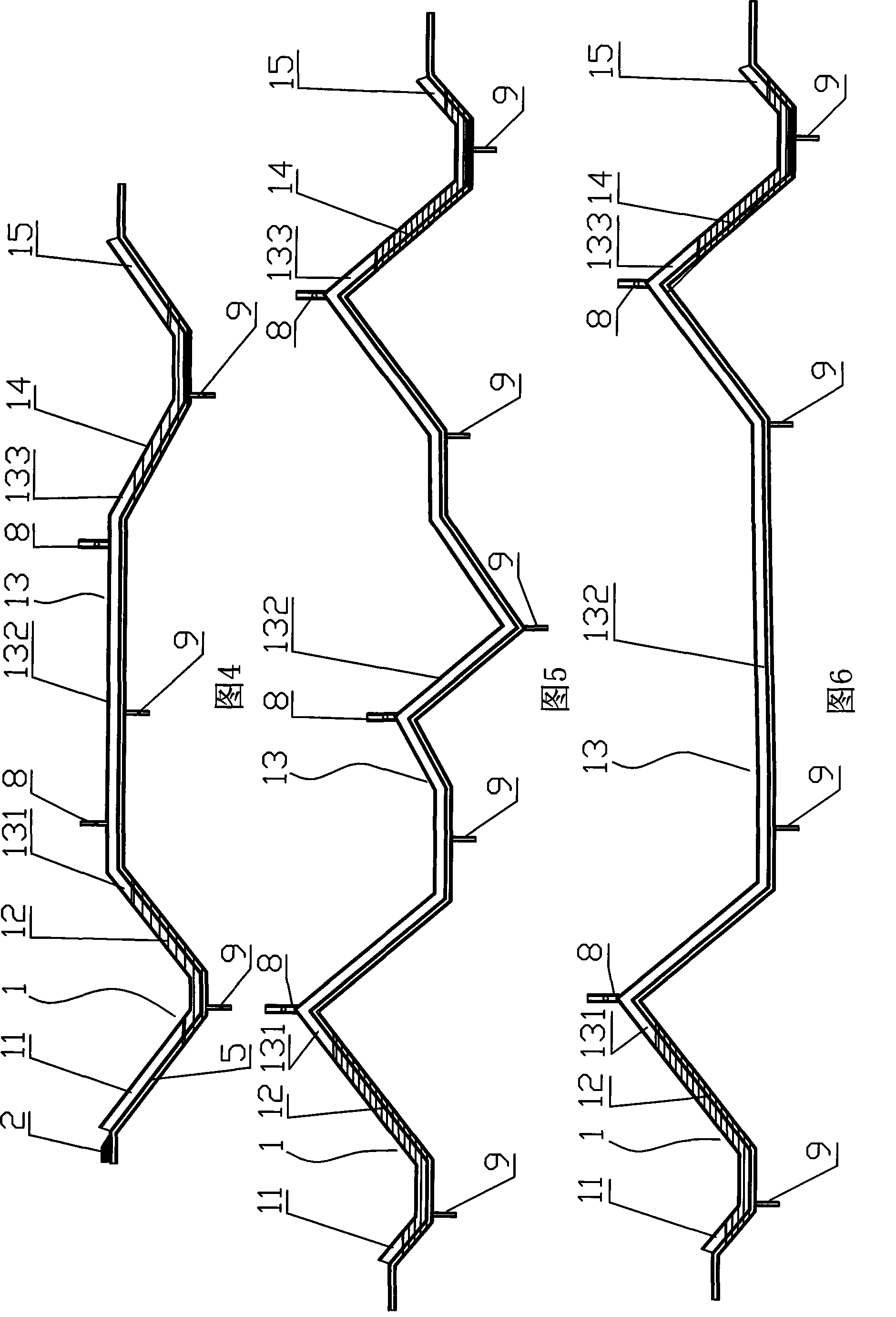
[0056] A magnetic levitation type sub-vacuum pipeline transportation system with valves in the pipeline (see Fig. 6), its basic structure and the running process of the train in the sub-vacuum pipeline are all the same as in Embodiment 1, wherein its basic structure includes sub-vacuum pipeline 1 and Airtight maglev train 2, a life support system is installed in the train body 2, and the sub-vacuum pipeline 1 is composed of an inlet atmospheric normal pressure downhill section 11, an inlet water sealing section 12, and a sub-vacuum section connected in sequence. 13. The outlet water sealing section 14 and the outlet atmospheric atmospheric pressure uphill section 15 are composed of five parts. The sub-vacuum section 13 is divided into a sub-vacuum rising section 131, a sub-vacuum middle section 132 and a sub-vacuum descending section 133, wherein, The sub-vacuum m...

Embodiment 3

[0058] Example 3: Wheel-rail sub-vacuum pipeline transportation system

[0059] A wheel-rail type sub-vacuum pipeline transportation system, its basic structure and the running process of the train in the sub-vacuum pipeline are the same as in Embodiment 1, the difference is that the bottom of the sub-vacuum pipeline 1 is equipped with rails, and the bottom of the train 2 It is mounted on wheels and driven by conventional electrified train motors.


PUM


Abstract

The invention discloses a transport system and a producing method of a sub-vacuum duct in a rail transport system. The transport system of the sub-vacuum duct comprises the sub-vacuum duct and a closed train, wherein the sub-vacuum duct comprises a downslope section of inlet normal atmosphere, a closed section of inlet liquid, a sub-vacuum section, a closed section of outlet liquid and an upslopesection of outlet normal atmosphere, the cross section of the duct is in an elliptical shape, silencing materials, force-bearing components, a vent valve, a drain valve, and the like are installed onthe duct, the train is an amphibious train, and the body of the train is made of warer-proof materials. The producing method of the sub-vacuum duct comprises the following steps: A. producing the bodyof the duct; B. installing the vent valve and the drain valve; and C. generating sub-vacuum: producing the duct into a sub-vacuum duct by a method for generating sub-vacuum by pumping liquid. The invention solves the problems of high manufacturing cost of sub-vacuum ducts, inconvenience for passengers to get on and get off the train when the train passes through the sub-vacuum duct and influenceon the vacuum state of the duct. Meanwhile, the invention has the advantages of high efficiency, low energy consumption, simple equipment, and the like.

Description

Technical field: [0001] The invention relates to a railway transportation system and a manufacturing method thereof, in particular to a sub-vacuum pipeline transportation system and a manufacturing method of the sub-vacuum pipeline. Background technique: [0002] At present, high-speed train transportation systems including wheel-rail type and maglev type are all running in an open natural environment. Since the total resistance of the train = rolling mechanical resistance + mechanical loss resistance + air momentum resistance + outflow aerodynamic resistance, in general When the speed of the train is 150-170 kilometers per hour, 75% of the train power is consumed on air resistance, and the faster the train runs, the greater the proportion of air resistance. It can be seen that the power of the train is mainly used to overcome The air resistance of the train running at high speed, but the power needed to overcome the frictional resistance of the train itself is very little, ...

Claims


Application Information

Patent Timeline
Patent Type & Authority Patents(China)
IPC IPC(8): B61B13/10
Inventor 谢建新
Owner 谢建新
Why Eureka
Eureka Blog
Learn More