Industrial electronic endoscope

An electronic endoscope and endoscope technology, applied in telescopes, optics, instruments, etc., can solve the problems of fiber-optic industrial endoscopes, such as the use distance and life limit, the heavy weight of the probe part, and the image clarity of broken wires. Achieve the effect of long service life, convenient operation and high resolution

Active Publication Date: 2009-10-07
SHANGHAI MUNICIPAL ELECTRIC POWER CO +1
View PDF0 Cites 15 Cited by
  • Summary
  • Abstract
  • Description
  • Claims
  • Application Information

AI Technical Summary

Problems solved by technology

Due to the number of bending times and the large bending angle of the optical fiber, it is easy to break the wire and make the image clarity worse, and the longer the optical fiber is used, the less clear the image is, and the weight of the probe part is also heavier. , so the use distance and life of fiber optic industrial endoscopes are limited

Method used


Image

  • Industrial electronic endoscope
  • Industrial electronic endoscope
  • Industrial electronic endoscope

Examples


Embodiment Construction

[0015] Below in conjunction with the accompanying drawings, the features of the present invention and other related features will be described in further detail by embodiments, so as to facilitate the understanding of those skilled in the same industry:

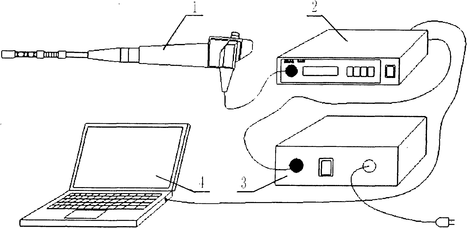
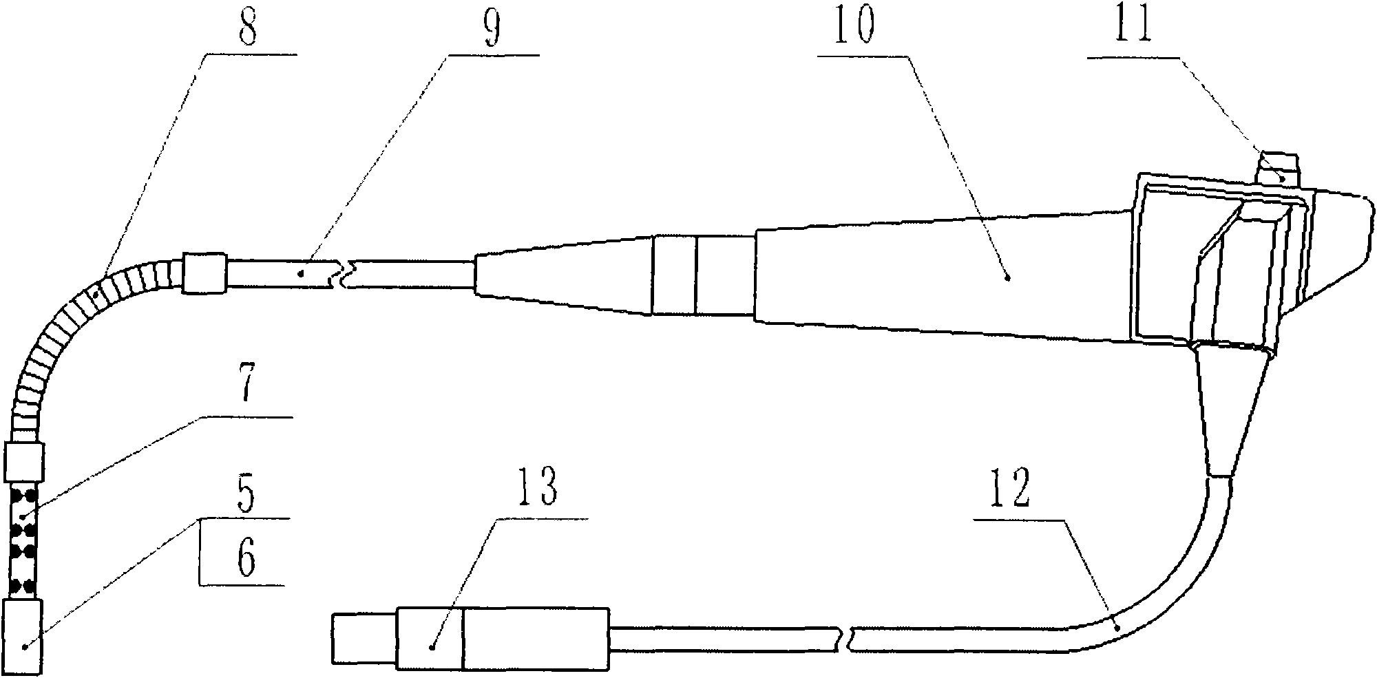
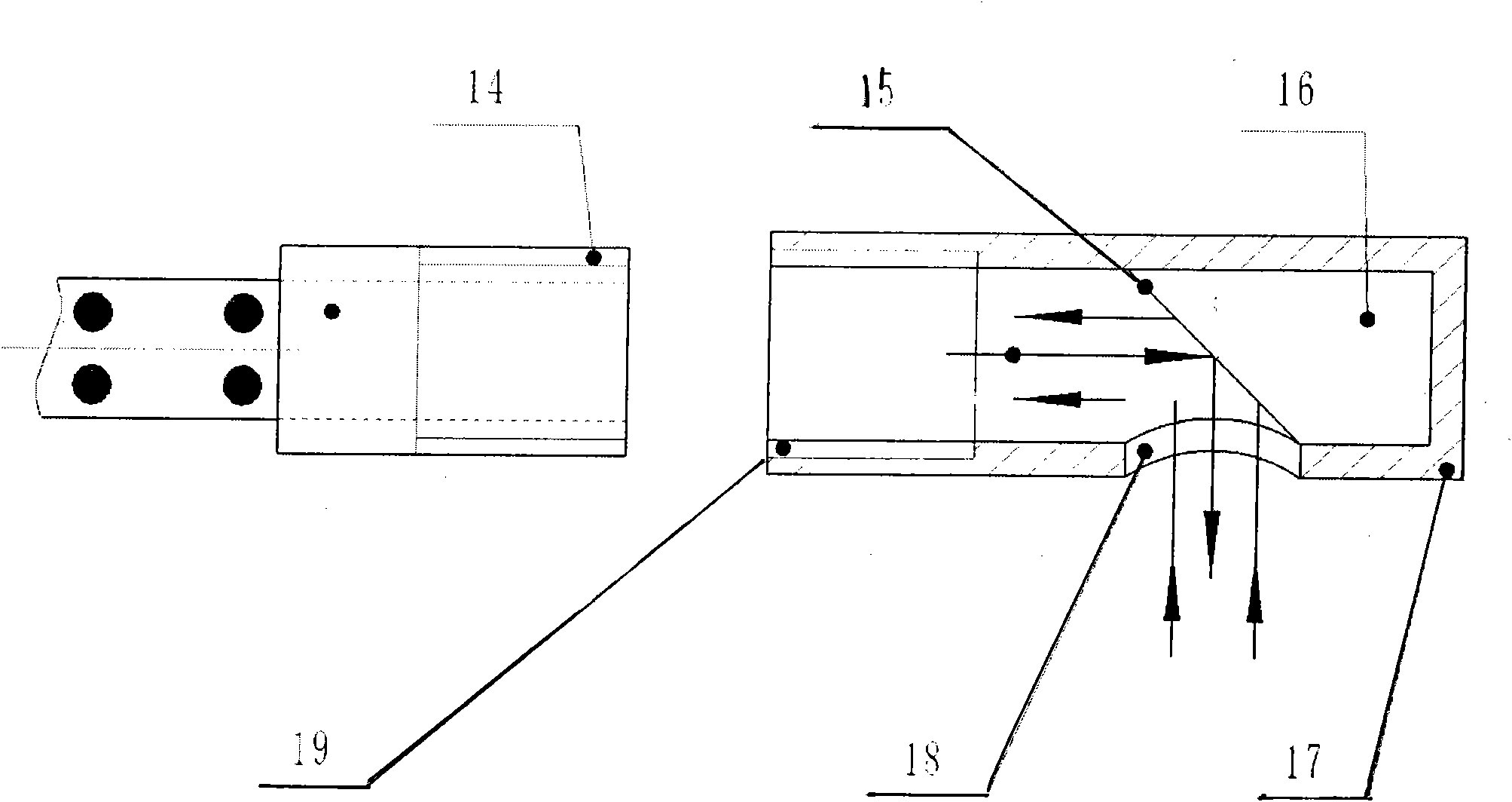
[0016] like Figure 1-3 As shown, numerals 1-19 respectively represent: endoscope probe 1, image signal conversion processing device 2, power supply 3, computer 4, CCD imaging device 5, LED light-emitting tube 6, operable hose 7, metal snake skin tube 8 , metal straight pipe 9, handle 10, operating mechanism 11, signal transmission line 12, connecting plug 13, external thread 14, coating layer 15, cylinder 16, side view corner mirror housing 17, lighting observation hole 18, internal thread 19 .

[0017] like figure 1 As shown, the industrial electronic endoscope device is composed of an endoscope probe 1 , an image signal conversion processing device 2 , a power supply 3 , and a computer 4 . The endoscopic probe 1 shoots ...


PUM


Abstract

The invention relates to a nondestructive detection apparatus, in particular a new industrial electronic endoscope for nondestructive detection. The new industrial electronic endoscope includes an endoscope probe that is connected with an image processing device through a connecting tube, wherein the endoscope probe is composed of a CCD imaging device and an LED light emitting tube; an image signal emitted from the CCD imaging device is transmitted to the image signal processing device through a transmission line disposed in the connecting tube. Compared with the industrial fibre endoscope, the advantages of the invention lie in that it has clear image, vivid colour, high resolution, large effective probing range, small volume and convenient operation and long service.

Description

technical field [0001] The invention relates to a nondestructive testing device, in particular to a novel industrial electronic endoscope suitable for nondestructive testing. Background technique [0002] The main working principle of the current industrial fiber optic endoscope is: the light emitted by the light source is transmitted to the front end of the probe through the light-transmitting optical fiber to the front end of the probe to illuminate the inspected part, and then a set of objective lenses in the probe will image the inspected part and then pass through Another set of optical fibers is sent out, and the image of the inspected part can be observed through the eyepiece. Due to the bending times and bending angle of the optical fiber, it is easy to break the wire, which makes the image clarity worse, and the longer the length of the optical fiber is, the less clear the image is, and the weight of the probe part is also heavier. , so the use distance and life of...

Claims


Application Information

Patent Timeline
Patent Type & Authority Applications(China)
IPC IPC(8): G02B23/24G01N21/84
Inventor 钱维忠姚建歆周陶宏姚明诸谧玮廖天明王乃盾宋若槑刘运中
Owner SHANGHAI MUNICIPAL ELECTRIC POWER CO
Why Eureka
Try Eureka